
Polarization Beam Splitter-Polarization Rotator Structure

a rotator and beam technology, applied in the field of polarization beam splitterpolarization rotator structure, can solve the problems of affecting the ultimate performance, yield, cost, error introduced into the signal, inefficient split of te and/or tm modes, inefficient rotation of te or tm modes,

Active Publication Date: 2008-01-24
INFINERA CORP
View PDF32 Cites 47 Cited by
  • Summary
  • Abstract
  • Description
  • Claims
  • Application Information

AI Technical Summary

Benefits of technology

[0056] From the above description, it is clear that the present invention is well adapted to carry out the objects and to attain the advantages mentioned herein as well as those inherent in the invention. While presently preferred embodiments of the invention have been described for purposes of this disclosure, it will be understood that numerous changes may be made which will readily suggest themselves to those skilled in the art and which are accomplished within the spirit of the invention disclosed and claimed.

Problems solved by technology

However, many devices remain polarization sensitive to some degree, and this affects ultimate performance, yield, and cost.
However, when an input light signal is split, or when a signal is rotated, there is usually error introduced into the signal due to inefficiencies in the polarization beam splitter or in the polarization rotator.
The error comprises inefficiently split TE and / or TM modes, or inefficiently rotated TE or TM modes.

Method used


Image

  • Polarization Beam Splitter-Polarization Rotator Structure
  • Polarization Beam Splitter-Polarization Rotator Structure
  • Polarization Beam Splitter-Polarization Rotator Structure

Examples


Embodiment Construction

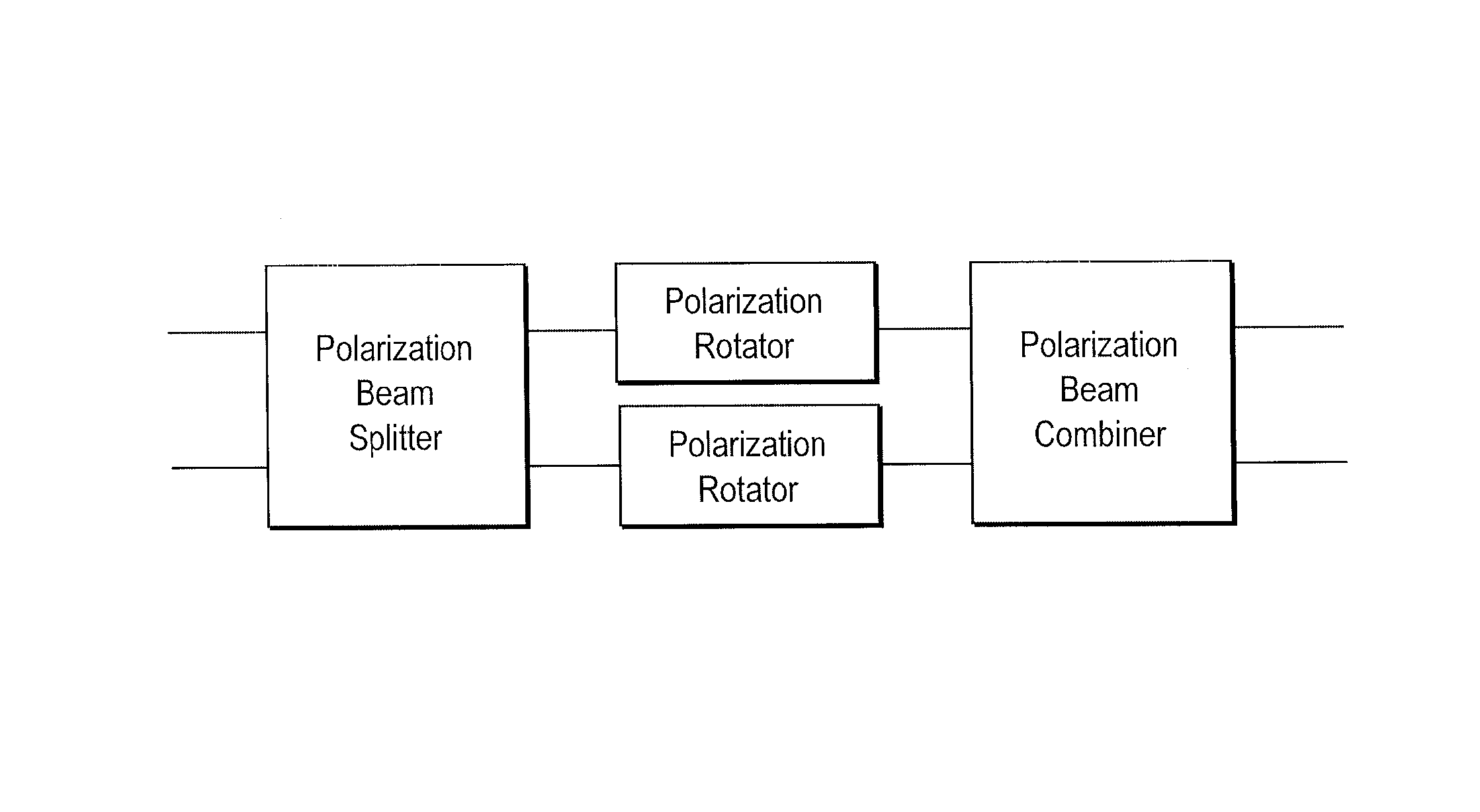
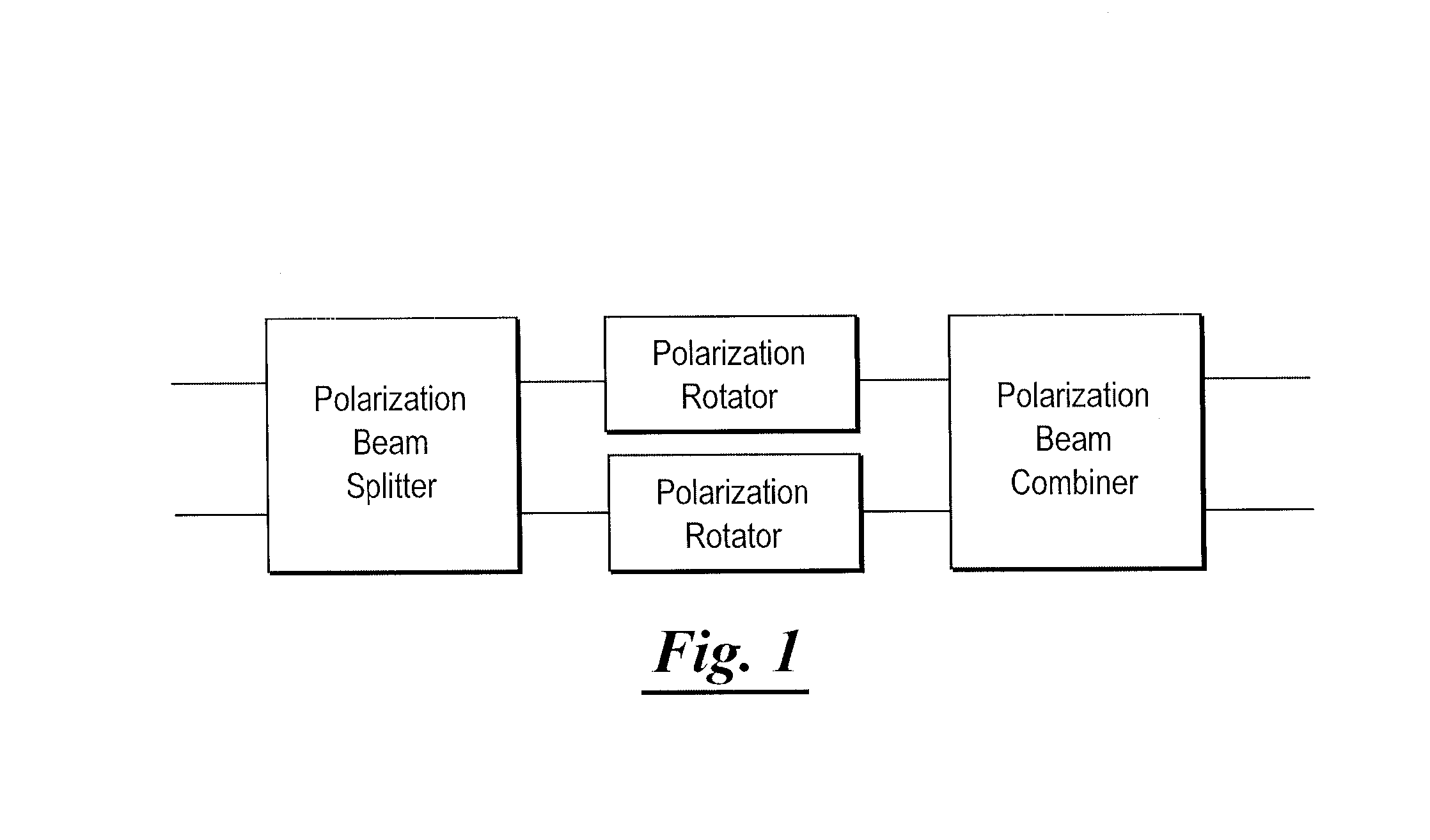
[0015] The present invention contemplates a polarization beam splitter-polarization rotator-polarization beam combiner structure comprising a pair of polarization rotators having a polarization beam splitter operatively connected to the input ends of the two polarization rotators, and a polarization beam combiner operatively connected to the output ends of the two polarization rotators, and a method of purifying a light signal comprising TE and TM modes.

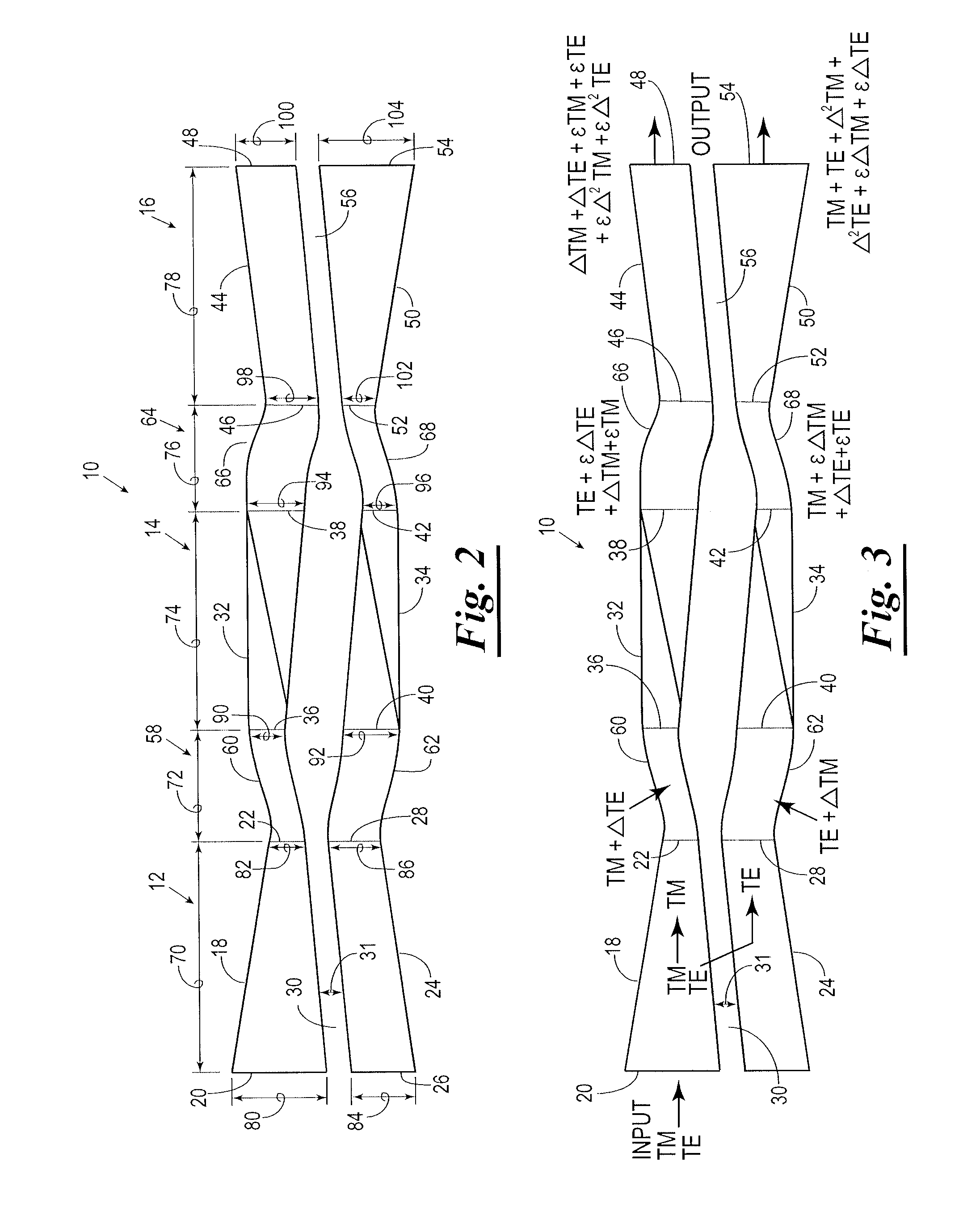
[0016] In the system and method of the present invention, polarized light comprising both TE and TM modes, is split into separate TE and TM modes (and error components), rotated to enhance the homogeneity of the TE and TM modes, and then recombined whereby undesired polarization error and leakage modes are separated from the primary TE and TM modes to provide a primary light output which is highly purified in the TE and TM modes such that only second order error modes remain in the primary output signal.

[0017] Shown in FIG. 1 is a ...


PUM


Abstract

A polarization beam splitter-polarization rotator-polarization beam combiner optical structure comprising a pair of polarization rotators having a polarization beam splitter associated with the input ends of the two polarization rotators, and a polarization beam combiner associated with output ends of the two polarization rotators, and a method of purifying a light signal comprising TE and TM modes by disassociating the primary TE and TM modes from first order splitter and rotation error components.

Description

CROSS-REFERENCE TO RELATED APPLICATIONS [0001] This application is a continuation-in-part of U.S. Ser. No. 11 / 222,358, filed Sep. 8, 2005. The present application is also a continuation-in-part of U.S. Ser. No. 11 / 495,201, filed on Jul. 28, 2006, each of which is hereby expressly incorporated herein by reference in its entirety.STATEMENT REGARDING FEDERALLY SPONSORED RESEARCH OR DEVELOPMENT [0002] Not applicable. BACKGROUND OF THE INVENTION [0003] The present invention relates generally to methods and apparatus for separating polarization modes of an input optical signal, rotating the polarization modes, then recombining the rotated polarization modes. [0004] Light is a vector field that has two primary and orthogonal polarization states or vector directions. Generally, the polarization states are referred to as the S and P polarizations in free space optics, or the TE (Transverse Electric) and TM (Transverse Magnetic) modes of optical waveguides. The performance of optical waveguid...

Claims


Application Information

Patent Timeline
IPC IPC(8): G02B6/26
CPCG02B6/1228G02B6/126G02B6/136G02B27/283G02B6/2766G02B6/2773G02B6/272
Inventor LITTLE, BRENT E.CHEN, WEI
Owner INFINERA CORP
Learn More