Ultrasonic examination apparatus

a technology probe, which is applied in the field of ultrasonic examination apparatus, can solve the problems of increasing the number of wirings with increasing the number of elements, the number of cables connecting the probe and the ultrasonic examination apparatus main body, and the manufacture process of the microscope and other problems, to achieve the effect of reducing the number of wirings to be connected to the multi-row array, reducing the number of cables connecting the probe and the ultrasonic examination apparatus main body, and reducing the number of prob

Inactive Publication Date: 2008-01-24
FUJIFILM CORP
View PDF7 Cites 26 Cited by
  • Summary
  • Abstract
  • Description
  • Claims
  • Application Information

AI Technical Summary

Benefits of technology

[0025] Accordingly, in view of the above-mentioned points, a purpose of the present invention is to provide an ultrasonic examination apparatus in which a number of wirings for connecting a probe to an ultrasonic examination apparatus main body can be reduced, and the expansion of sidelobes can be suppressed even when an ultrasonic beam is deflected in the elevation direction.
[0027] According to the present invention, plural elements are grouped in each element column of the multirow array and drive signals are supplied with respect to each group, and therefore, the number of wirings to be connected to the multirow array can be reduced. Thereby, the number of cables connecting the probe to the ultrasonic examination apparatus main body can be reduced, and thus, the operability of the probe can be improved and the physical burden on the patient to be examined can be reduced. Further, the combinations of elements to be grouped can be optimized according to the transmission direction of an ultrasonic beam, and therefore, a good quality ultrasonic beam can be transmitted regardless of the transmission direction of the ultrasonic beam. Thereby, image quality of ultrasonic images can be improved.

Problems solved by technology

However, since microelements are used in the 2D array, the manufacturing process thereof is microscopic and complicated.
Further, the number of wirings increases with increase in the number of elements, and therefore, a problem that a cable connecting the probe and the ultrasonic examination apparatus main body becomes thicker arises.
Especially, the thicker cable is a fatal flaw because severe constraints in size are imposed on the ultrasonic endoscope to be inserted into a living body.
However, in the elevation direction, the width of the element is larger than the wavelength of the ultrasonic waves, and thus, constraints are imposed on the range where the ultrasonic beam can be deflected, and there is no degree of freedom equal to that in the azimuth direction.
However, according to JP-P2003-130859A, there is a problem that the number of switches for switching the groups increases.
If the large number of switches are provided at the probe side, the probe itself is upsized, and that is a fatal flaw in the ultrasonic endoscope.
However, if the 1.75D array is adopted in the weighted arrangement for deflection of the ultrasonic beams, a problem in increase of sidelobes arises.

Method used


Image

  • Ultrasonic examination apparatus
  • Ultrasonic examination apparatus
  • Ultrasonic examination apparatus

Examples


Embodiment Construction

[0044] Hereinafter, preferred embodiments of the present invention will be explained in detail with reference to the drawings. The same reference numerals will be assigned to the same component elements and the description thereof will be omitted.

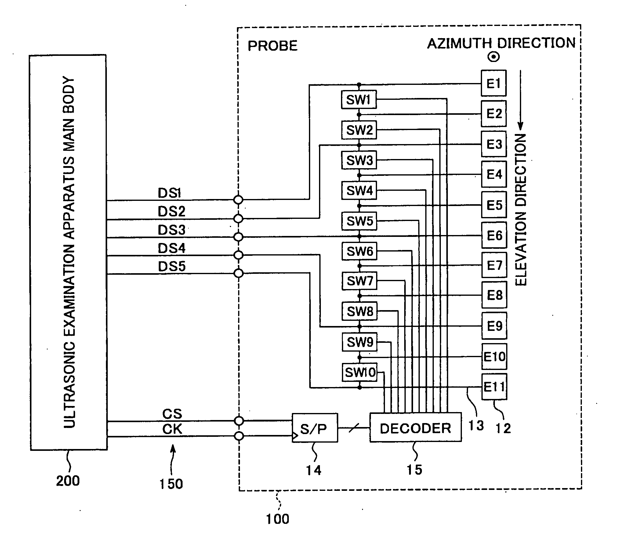
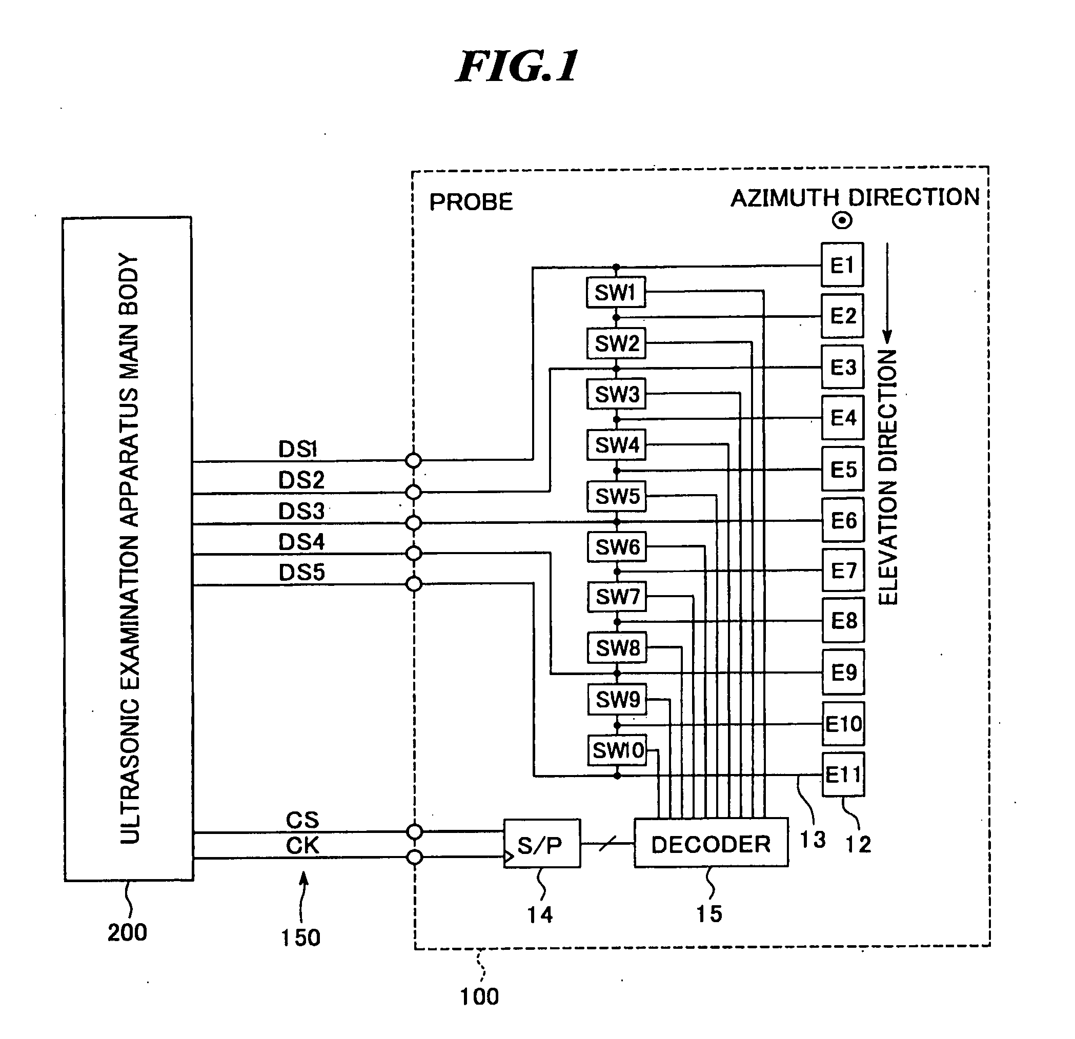
[0045]FIG. 1 is a block diagram showing a configuration of an ultrasonic examination apparatus according to one embodiment of the present invention. The ultrasonic examination apparatus includes a probe 100, an ultrasonic examination apparatus main body 200, and a cable 150 for connecting them to each other. The probe 100 is suitable for use in an ultrasonic endoscope examination by being inserted into a body cavity of an object to be inspected so as to observe the condition within the object, but also suitable for typical ultrasonic examination by being in contact with the body surface of the object.

[0046] As shown in FIG. 1, the probe 100 includes an ultrasonic transducer array 10 including plural element rows of E1 to E11, plural switc...


PUM


Abstract

An ultrasonic examination apparatus in which a number of wirings for connecting a probe to an ultrasonic examination apparatus main body can be reduced, and sidelobes can be suppressed even when an ultrasonic beam is deflected. The ultrasonic examination apparatus includes: a probe having a multirow array formed by arranging plural element rows in parallel with one another, each element row including one-dimensionally arranged ultrasonic transducers, and switches for opening and closing electric connections between respective adjacent two elements in each element column of the multirow array to form element groups; a system control unit for controlling the switches according to a transmission / reception direction of an ultrasonic beam; a drive signal generating unit for generating drive signals to be respectively supplied to the element groups; and signal processing units for processing reception signals respectively outputted from the element groups to generate an image signal.

Description

BACKGROUND OF THE INVENTION [0001] 1. Field of the invention [0002] The present invention relates to an ultrasonic examination apparatus for transmitting ultrasonic waves toward an object to be inspected and receiving ultrasonic echoes from the object to generate ultrasonic images, and specifically, to an ultrasonic examination apparatus including an ultrasonic endoscope in which an ultrasonic transducer array is combined with an endoscope to be inserted into a body cavity of the object for optical observation of the condition within the object. [0003] 2. Description of a Related Art [0004] Ultrasonic imaging technologies for generating images showing tissue conditions within an object to be inspected by receiving ultrasonic echoes, that is, ultrasonic waves transmitted toward the interior of the object and reflected by structures (organs and so on) within the object and performing signal processing thereon are widely used in various fields including medical fields. An apparatus for...

Claims


Application Information

Patent Timeline
Patent Type & Authority Applications(United States)
IPC IPC(8): A61B8/00
CPCA61B8/00B06B1/0629G01S15/8927G01S15/8925G01S7/5208A61B8/4494
Inventor SETO, YASUHIRO
Owner FUJIFILM CORP
Why Eureka
Try Eureka