Electrically heated catalytic converter and method of manufacturing the same

a catalytic converter and electric heating technology, applied in the direction of physical/chemical process catalysts, liquid/solution decomposition chemical coatings, separation processes, etc., can solve the problems of excessive hardness of protective films, deterioration of gas barrier properties of protective films, cracking of protective films, etc., and achieve excellent gas barrier properties

Active Publication Date: 2020-08-11
TOYOTA JIDOSHA KK +1
View PDF13 Cites 0 Cited by
  • Summary
  • Abstract
  • Description
  • Claims
  • Application Information

AI Technical Summary

Benefits of technology

[0013]In the electrically heated catalytic converter according to the disclosure, the protective film, which is formed on the surface of the electrode member, is formed of i) Al2O3, ii) SiO2, iii) a composite material of Al2O3 and SiO2, or iv) a composite oxide including Al2O3, SiO2, or a composite material of Al2O3 and SiO2 as a major component, and the protective film has a configuration in which the entire portion is formed of an amorphous structure or in which a partially crystalline glass structure having a crystallization rate of 30 vol % or lower with respect to the entire portion of the protective film is provided. As a result, the protective film has an oxidation resistance temperature of 1000° C. or higher. The protective film has an amorphous structure or a partially crystalline glass structure, and the thickness thereof is in a range of 100 nm to 2 μm. As a result, thermal stress is not likely to be generated, and thus the protective film is not likely to crack. The thickness of the protective film may be in a range of 100 nm to 1 μm.
[0015]The protective film has a configuration in which the entire portion is formed of an amorphous structure or in which a partially crystalline glass structure having a crystallization rate of 30 vol % or lower with respect to the entire portion of the protective film is provided. That is, the protective film has no crystal structure or a small amount of crystal structure. Therefore, the Young's modulus or thermal expansion coefficient of the protective film can be suppressed to be low, and thus the protective film has cracking resistance performance.
[0021]According to the present inventors, it is verified that the protective film included in the electrically heated catalytic converter according to the disclosure has an oxidation resistance temperature of 1000° C. or higher, more specifically, 1000° C. to 1100° C. The electrode member may be a single member made of a metal or a ceramic or a composite member made of a metal and a ceramic, the electrode member is constituted with a surface electrode and a wiring fixing layer and that the electrode member may be a porous member in which a porosity of the surface electrode and the wiring fixing layer may 5% or higher. According to this configuration, the thermal expansion coefficients of the electrode member and the substrate are substantially the same, and thermal shock resistance can be increased when the electrically heated catalytic converter is actually used in an engine. The thermal expansion coefficients only has to be substantially the same to the extent that the catalytic converter is not damaged by thermal shock caused by a difference in thermal expansion coefficient when actually used in an engine.
[0024]The present inventors found that, in a case where the firing temperature is about 700° C., the film-forming rate of the protective film is increased, and residual stress is generated in the formed protective film, which is not preferable.
[0027]In this way, a nanomaterial of Al2O3, a nanomaterial of SiO2, or the like is used as a material of a protective film, and a sol-gel solution is used for a hydrolysis reaction to form the protective film. As a result, a dense protective film having excellent gas barrier properties against O2 gas or the like can be formed.
[0028]As can be seen from the above description, in the electrically heated catalytic converter and the method of manufacturing the same according to the present disclosure, the protective film that is formed on a surface of the electrode member is formed of i) Al2O3, ii) SiO2, iii) a composite material of Al2O3 and SiO2, or iv) a composite oxide including Al2O3, SiO2, or a composite material of Al2O3 and SiO2 as a major component, the protective film has a configuration in which the entire portion is formed of an amorphous structure or a partially crystalline glass structure having a crystallization rate of 30 vol % or lower with respect to the entire portion of the protective film is provided, and a thickness of the protective film is in a range of 100 nm to 2 μm. As a result, the protective film can be formed at a firing temperature of 500° C. or lower, and the electrically heated catalytic converter including the protective film can be provided which has an oxidation resistance temperature of 1000° C. or higher and is not likely to crack and in which thermal stress is not likely to be generated.

Problems solved by technology

On the other hand, the protective film of the electrode member constituting the electrically heated catalytic converter requires an oxidation resistance temperature of 1000° C. or higher, and the development of a new protective film alternative to the protective film formed of Cr2O3 or the like is an urgent issue.
In a case where the thickness of the protective film is more than 2 μm, the protective film becomes excessively hard, and the protective film may crack due to a difference in thermal expansion between the substrate and the comb-shaped wiring.
In a case where the thickness of the protective film is less than 100 nm, the gas barrier properties thereof deteriorate.

Method used


Image

  • Electrically heated catalytic converter and method of manufacturing the same
  • Electrically heated catalytic converter and method of manufacturing the same
  • Electrically heated catalytic converter and method of manufacturing the same

Examples


embodiment

[0038](Embodiment of Electrically Heated Catalytic Converter and Method of Manufacturing the Same)

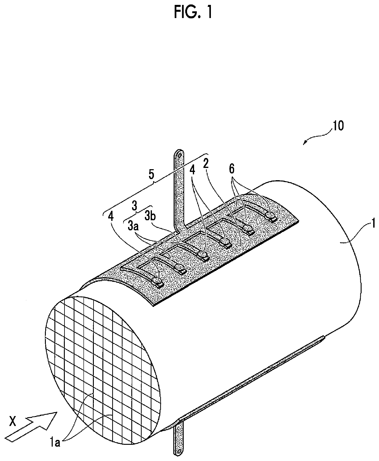
[0039]FIG. 1 is a schematic diagram showing an embodiment of an electrically heated catalytic converter (EHC) according to the disclosure. An electrically heated catalytic converter 10 shown in the drawing is incorporated into an exhaust system for exhaust gas. Specifically, in the exhaust system, an engine (not shown), the electrically heated catalytic converter (EHC) 10, a three-way catalytic converter (not shown), a sub muffler (not shown), and a main muffler (not shown) are disposed in this order and are connected to each other through a system pipe. When the engine starts, a noble metal catalyst constituting the electrically heated catalytic converter 10 is heated to a predetermined temperature as soon as possible, exhaust gas flowing from the engine is purified by the noble metal catalyst, and a portion of the exhaust gas which is not purified by the electrically heated catalytic ...


PUM

PropertyMeasurementUnit
thicknessaaaaaaaaaa
porosityaaaaaaaaaa
temperatureaaaaaaaaaa

Abstract

Provided is an electrically heated catalytic converter including at least a conductive substrate and an electrode member that is fixed to the substrate, in which a protective film is formed on a surface of at least a portion of the electrode member. In the electrically heated catalytic converter, at least a portion of the protective film is formed of Al2O3, SiO2, a composite material of Al2O3 and SiO2, or a composite oxide including Al2O3, SiO2, or a composite material of Al2O3 and SiO2 as a major component, the protective film has an amorphous structure or a partially crystalline glass structure having a crystallization rate of 30 vol % or lower with respect to the entire portion of the protective film, and a thickness of the protective film is in a range of 100 nm to 2 μm.

Description

INCORPORATION BY REFERENCE[0001]The disclosure of Japanese Patent Application No. 2016-092642 filed on May 2, 2016 including the specification, drawings and abstract is incorporated herein by reference in its entirety.BACKGROUND1. Technical Field[0002]The present disclosure relates to an electrically heated catalytic converter that is disposed in an exhaust system for exhaust gas, and a method of manufacturing the same.2. Description of Related Art[0003]In various industries, various efforts to reduce environmental impacts have been made on a global scale. In particular, in the automobile industry, the development of techniques has progressed for the spread of not only a gasoline engine vehicle having superior fuel efficiency but also a so-called eco-car such as a hybrid vehicle or an electric vehicle and for further improvement in the performance of the vehicles.[0004]Incidentally, in an exhaust system for exhaust gas through which a vehicle engine and a muffler are connected to ea...

Claims


Application Information

Patent Timeline
Patent Type & Authority Patents(United States)
IPC IPC(8): F01N3/20B05D7/14H05B3/00H05B3/14B05D3/02B01J35/04B01J35/00B01J27/224B01J23/46B01J23/44B01J23/42B01D53/94B01J37/03B01J37/08C23C18/12H05B3/08F01N3/28H05B3/03H05B3/02
CPCB05D3/0254H05B3/0014B01J27/224F01N3/2828C23C18/1254B05D7/14B01J35/0033F01N3/2026B01J23/464B01J37/08H05B3/148H05B3/08H05B3/03B01J37/036C23C18/1295C23C18/1212C23C18/1275C23C18/122B01J23/42B01J23/44B01J35/04B01D53/9454B01J35/0006B01D2255/2092H05B2203/024B01D2255/407B01D2255/102B01D53/94F01N3/2013F01N3/28Y02T10/12
Inventor MORI, RENTAROKASAI, YOSHIYUKIOMIYA, YOSHIMASA
Owner TOYOTA JIDOSHA KK
Why Eureka
Try Eureka