
Method and Apparatus for Monitoring a Urea Injection System in an Exhaust Aftertreatment System

Inactive Publication Date: 2008-01-31
GM GLOBAL TECH OPERATIONS LLC
View PDF11 Cites 156 Cited by
  • Summary
  • Abstract
  • Description
  • Claims
  • Application Information

AI Technical Summary

Benefits of technology

[0006]In accordance with an embodiment of the invention, a method and monitoring system for an exhaust aftertreatment system is provided. A control module controls an injecting device operable to inject reductant into an exhaust gas feedstream upstream of a selective catalyst reduction device. The monitoring system is adapted to control a rate of dosing from the injecting device and, monitor inputs from a sensing device operative to monitor the selective catalyst reduction device. The sensing device can include an ammonia sensor, and, alternatively, a NOx sensor. Controlling the rate of dosing from the injecting device includes selectively intrusively c

Problems solved by technology

When an engine operates in a region lean of stoichiometry, a resultant typically includes increased combustion temperatures, leading to increased NOx emissions.
Typical urea injection control systems currently in use are not capable of controlling urea injection at very low flow rates, which typically occur at engine idle conditions and when a vehicle is decelerating, i.e. conditions when the engine is producing very low engine-out NOx emissions.
The catalyst is able to continue NOx reduction when the urea injection control system is not capable of controlled dosing, i.e., supplying a controlled amount of urea.
A fault occurring in an exhaust aftertreatment system employing a urea injection system leads to the system not operating as intended, resulting in customer dissatisfaction.

Method used


Image

  • Method and Apparatus for Monitoring a Urea Injection System in an Exhaust Aftertreatment System
  • Method and Apparatus for Monitoring a Urea Injection System in an Exhaust Aftertreatment System
  • Method and Apparatus for Monitoring a Urea Injection System in an Exhaust Aftertreatment System

Examples


Embodiment Construction

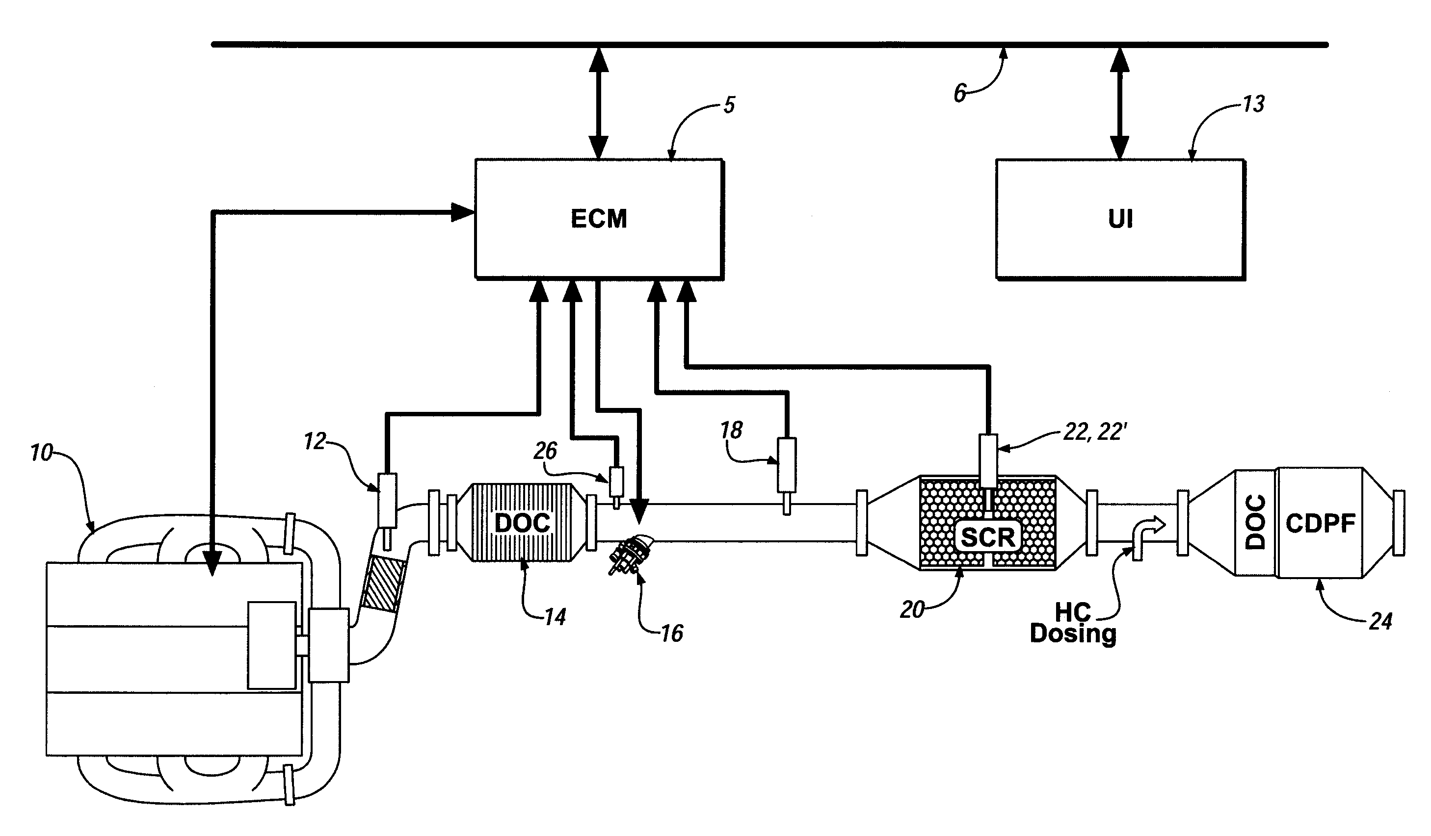
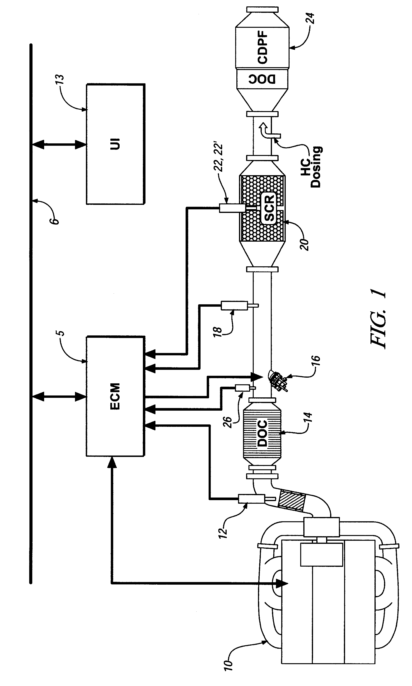
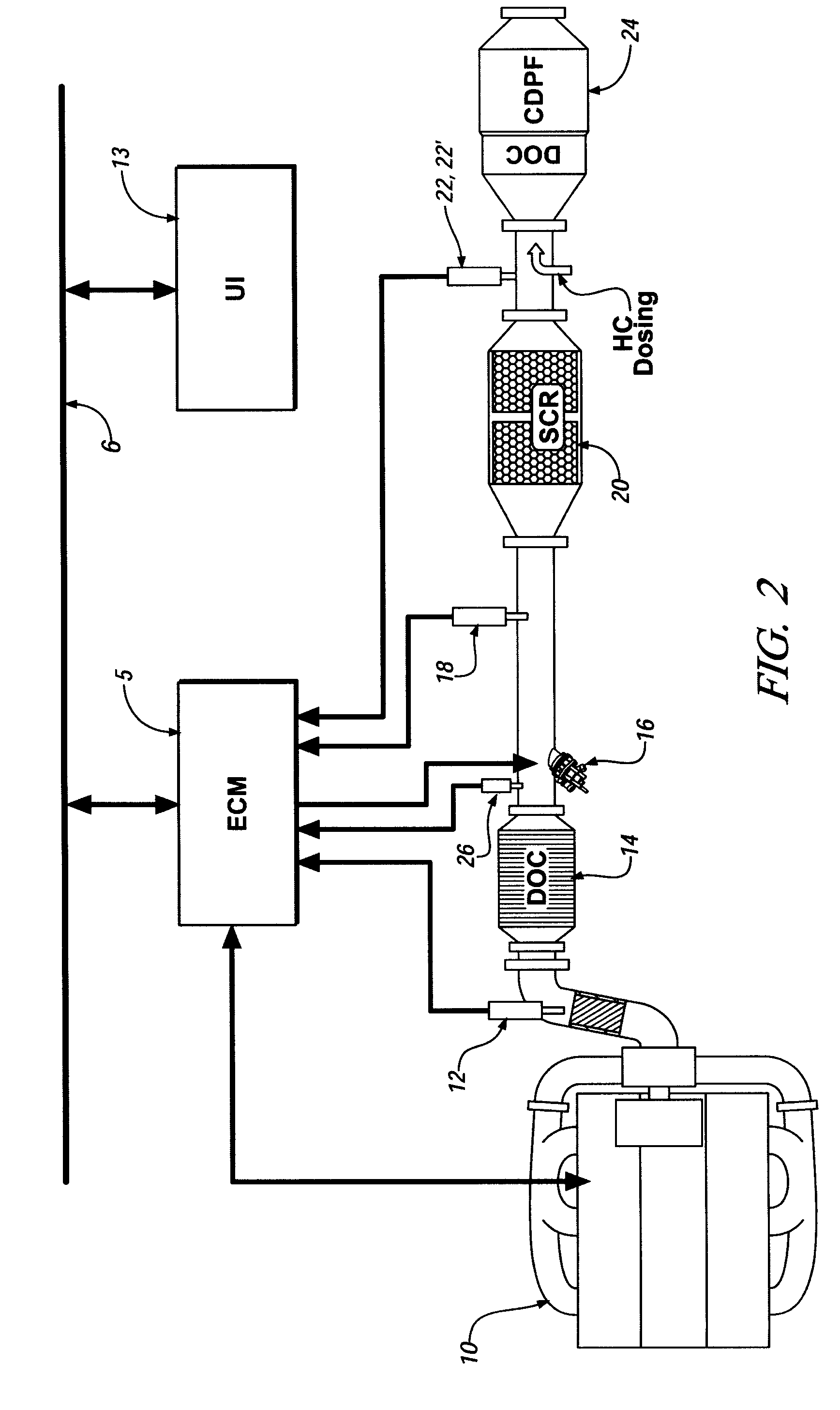
[0013]Referring now to the drawings, wherein the showings are for the purpose of illustrating the invention only and not for the purpose of limiting the same, FIGS. 1 and 2 comprise schematic diagrams depicting an internal combustion engine, exhaust aftertreatment system, and control system which has been constructed in accordance with embodiments of the present invention.

[0014]The exemplary engine and control system comprises a four-cycle internal combustion engine 10 and electronic engine control module 5. The exemplary engine comprises a diesel compression-ignition engine having an operating regime that is primarily lean of stoichiometry. Alternatively, the engine may comprise an engine using any one of a number of engine control strategies which operate lean of stoichiometry, e.g. homogeneous-charge compression-ignition engines, and lean-burn spark-ignition engines. The exemplary engine 10 includes a plurality of reciprocating pistons attached to a crankshaft, which is operably ...


PUM


Abstract

A monitoring system for an exhaust aftertreatment system is provided, comprising an injecting device operable to inject reductant into an exhaust gas feedstream upstream of a selective catalyst reduction device. The monitoring system comprises a control module, adapted to selectively intrusively control a rate of dosing from the injecting device and, monitor inputs from a sensing device. The sensing device can comprise an ammonia sensor, and, alternatively, a NOx sensor. The control module is adapted to discontinue the rate of dosing, and substantially increase and decrease the rate of dosing for a predetermined amount of time, and to identify a fault in the sensing device and the selective catalyst reduction device.

Description

TECHNICAL FIELD[0001]This invention pertains generally to exhaust aftertreatment systems for internal combustion engines.BACKGROUND OF THE INVENTION[0002]Manufacturers of internal combustion engines are continually developing new engine control strategies to satisfy customer demands and meet various regulations. One such engine control strategy comprises operating an engine at an air / fuel ratio that is lean of stoichiometry to improve fuel economy and reduce greenhouse gas emissions. Such engines include both compression-ignition (diesel) and lean-burn spark-ignition engines. When an engine operates in a region lean of stoichiometry, a resultant typically includes increased combustion temperatures, leading to increased NOx emissions.[0003]One proposed type exhaust aftertreatment system and control strategy for managing and reducing NOx emissions includes injection of urea into an exhaust gas feedstream upstream of a selective catalytic reduction (‘SCR’) catalytic device to cause a r...

Claims


Application Information

Patent Timeline
IPC IPC(8): F01N3/00F01N7/00
CPCF01N3/035F01N3/2066F01N3/36F01N11/00F01N2550/05F01N13/0093F01N2610/14Y02T10/47Y02T10/24F01N13/009F01N13/0097F01N2610/02Y02T10/12Y02T10/40
Inventor VIOLA, MICHAEL B.BROWN, DAVID B.PARATORE, MICHAEL J.
Owner GM GLOBAL TECH OPERATIONS LLC
Features
  • Generate Ideas
  • Intellectual Property
  • Life Sciences
  • Materials
  • Tech Scout
  • Unparalleled Data Quality
  • Higher Quality Content
  • 60% Fewer Hallucinations
Learn More