
Method for removing oilfield mineral scale from pipes and tubing

a technology of mineral scale and pipe pipe, which is applied in the field of improved methods for removing mineral scale from pipes and tubing, can solve the problems of scale formation to such an extent, flow restrictions, and salts may be incompatible with ions already contained,

Active Publication Date: 2008-01-31
EXKAL LTD
View PDF5 Cites 46 Cited by
  • Summary
  • Abstract
  • Description
  • Claims
  • Application Information

AI Technical Summary

Problems solved by technology

These salts may be incompatible with the ions already contained in the oil-containing reservoir.
These mineral scales may adhere to pipe walls as layers that reduce the inner bore of the pipe, thereby causing flow restrictions.
Not uncommonly, scale may form to such an extent that it may completely choke off a pipe.
Oilfield production operations may be compromised by such mineral scale.
Some mineral scales, such as barium sulphate, are very difficult to remove chemically, from tubing and, as such, the tubing is simply replaced with new tubing.
The scaled tubing may be removed for disposal, but the mineral scale that forms presents an environmental hazard.
While 238U and 232Th are found in many underground formations, they are not very soluble in the reservoir fluid.
While these radionuclides do not precipitate directly, they are generally co-precipitated in barium sulfate scale, causing the scale to be mildly radioactive.
This NORM poses a hazard to people coming into contact with it through irradiation and through breathing or ingestion of NORM particles.
Common operations used for removing scale from tubing may be slow and inefficient because each tube has to be individually treated if they are radioactive and access to the scaled internal surface of the tubing may be restricted.
Occasionally, contaminated tubing and equipment is simply removed and replaced with new equipment.
When the old equipment is contaminated with NORM, this scale encrusted equipment may not be disposed of easily because of the radioactive nature of the waste.
The dissolution of NORM scale and its disposal may be costly and hazardous.
In addition, a considerable amount of oilfield tubular goods and other equipment awaiting decontamination is presently sitting in storage facilities.
However, use of high pressure water jetting is generally time consuming, expensive, and may fail to thoroughly treat the contaminated area.
Further, chemical chelants such as EDTA and DTPA are expensive and require prolonged contact at elevated temperatures to dissolve the scale.

Method used


Image

  • Method for removing oilfield mineral scale from pipes and tubing
  • Method for removing oilfield mineral scale from pipes and tubing
  • Method for removing oilfield mineral scale from pipes and tubing

Examples


Embodiment Construction

[0024] In one aspect, embodiments of disclosed herein relate to a method of removing mineral scale from oilfield pipes and tubing. In particular, embodiments disclosed herein relate to a method of mechanically separating mineral scale from oilfield pipes and tubing. Further, as used herein, “pipes,”“tubing,” and “tubes” may be used interchangeably to describe embodiments without limiting the scope of the claims.

[0025] Mineral scale that may be removed from oilfield equipment in embodiments disclosed herein includes oilfield scales, such as, for example, salts of alkaline earth metals or other divalent metals, including sulfates of barium, strontium, radium, and calcium, carbonates of calcium, magnesium, and iron, metal sulfides, iron oxide, and magnesium hydroxide.

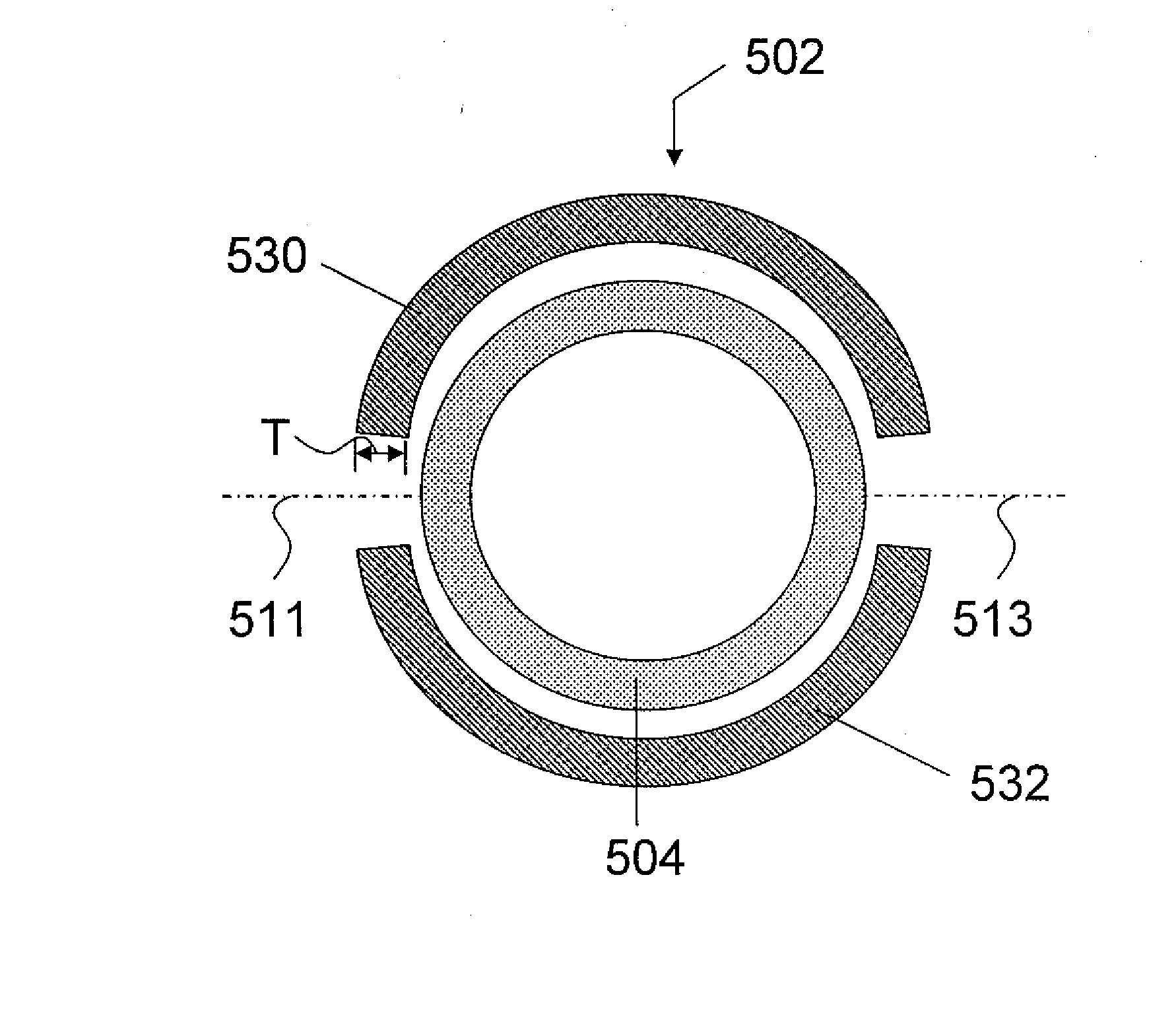
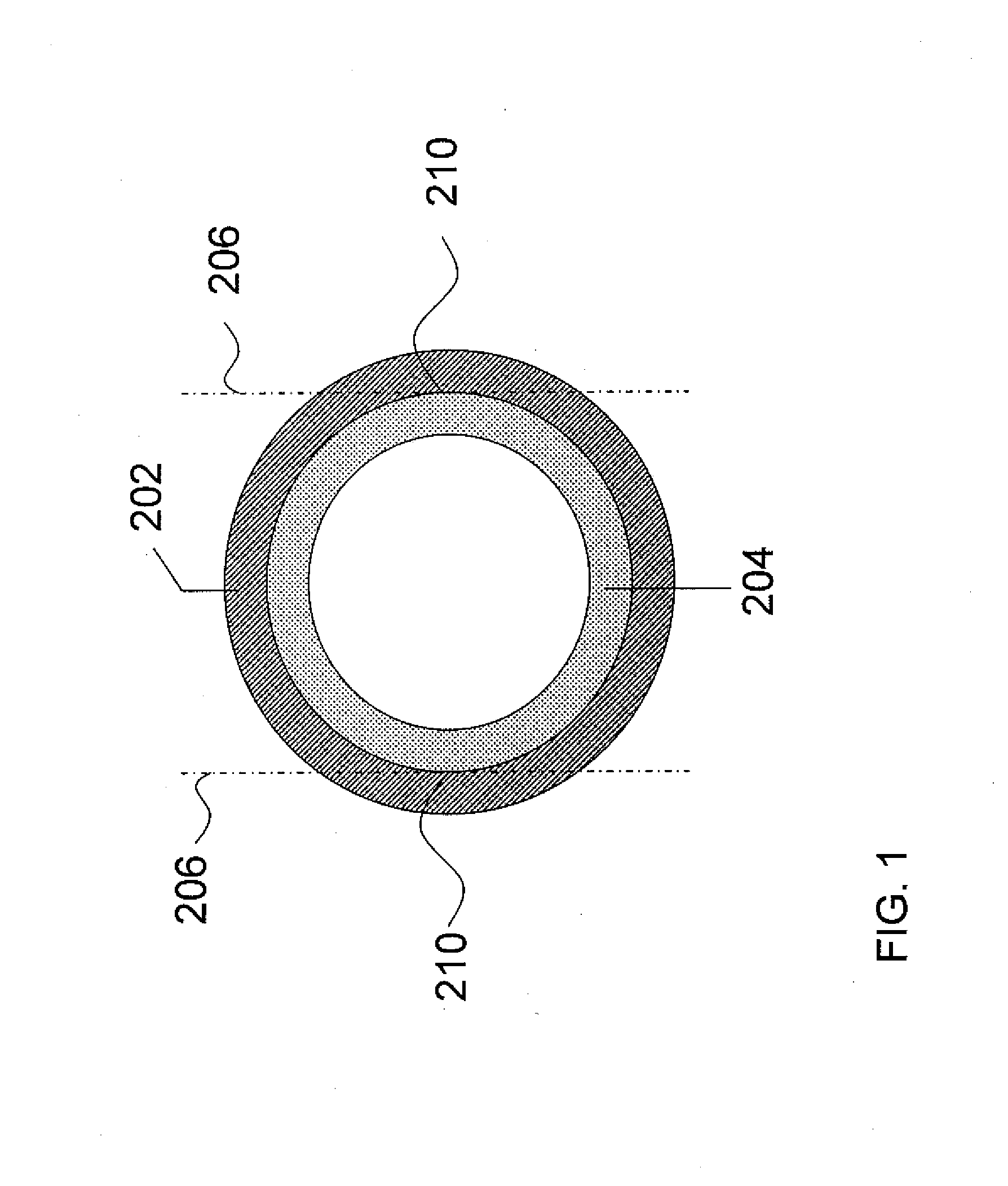
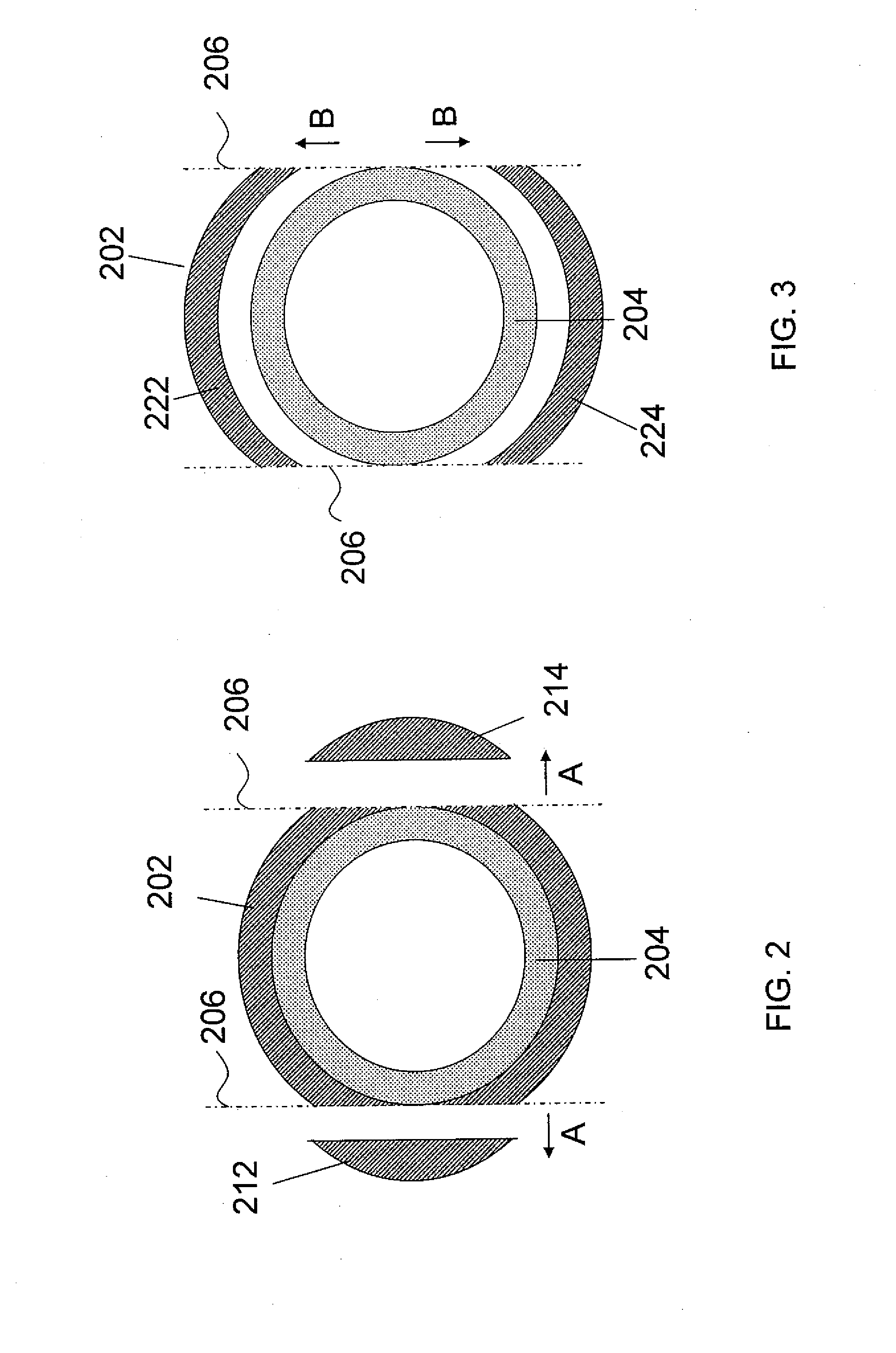
[0026] A method of removing or separating mineral scale from a tubular or pipe according to an embodiment disclose herein is shown in FIGS. 1-4. As shown in FIG. 1, a pipe 202 is encrusted with a layer of mineral scale 2...


PUM

PropertyMeasurementUnit
pressuresaaaaaaaaaa
lengthaaaaaaaaaa
thicknessaaaaaaaaaa

Abstract

A method for removing mineral scale from tubing is disclosed. The method may include the steps of making a first longitudinal cut along a length of the tubing, making a second longitudinal cut along a length of tubing, and removing a plurality of sections of tubing, wherein the sections of tubing are defined by the first and second longitudinal cuts.

Description

CROSS-REFERENCE TO RELATED APPLICATIONS [0001] This application, pursuant to 35 U.S.C. § 119(e), claims priority to U.S. Provisional Application Ser. No. 60 / 820,861, filed Jul. 31, 2006. That application is incorporated by reference in its entirety.BACKGROUND OF INVENTION [0002] 1. Field of the Invention [0003] The invention relates generally to pipes and tubing used in the oilfield. Specifically, the invention relates to an improved method for removing mineral scale from pipes and tubing. [0004] 2. Background Art [0005] Hydrocarbons (e.g., oil, natural gas, etc.) are obtained from a subterranean geologic formation (i.e., a “reservoir”) by drilling a wellbore that penetrates the hydrocarbon-bearing formation. In order for the hydrocarbons to be produced, that is, travel from the formation to the wellbore, and ultimately to the surface, at rates of flow sufficient to justify their recovery, a sufficiently unimpeded flowpath from the subterranean formation to the wellbore, and then to...

Claims


Application Information

Patent Timeline
Patent Type & Authority Applications(United States)
IPC IPC(8): E21B37/00
CPCB26D3/001E21B37/00Y10T29/4506Y10T29/4511Y10T29/45F28G13/00B08B9/02B26D3/00
Inventor KEATCH, RICHARD W.RAY, SIMON K.
Owner EXKAL LTD
Learn More