Oscillator

a technology of oscillator and oscillator, which is applied in the direction of pulse generator, pulse generation by logic circuit, pulse technique, etc., can solve the problems of inversely proportional to the voltage square the error of the long channel mos transistor and the 20% error of the high-r poly caused by process variation

Inactive Publication Date: 2008-01-31
PRINCETON TECHNOLOGY
View PDF4 Cites 5 Cited by
  • Summary
  • Abstract
  • Description
  • Claims
  • Application Information

AI Technical Summary

Problems solved by technology

Further, the error of the high-R poly caused by process variation may be 20%, and that of the long channel MOS transistor caused by process variation may be 10%.
In addition, the error of the long channel MOS transistor is inversely proportional to the voltage square.

Method used


Image

  • Oscillator
  • Oscillator
  • Oscillator

Examples


Embodiment Construction

[0021]The following description is of the best-contemplated mode of carrying out the invention. This description is made for the purpose of illustrating the general principles of the invention and should not be taken in a limiting sense. The scope of the invention is best determined by reference to the appended claims.

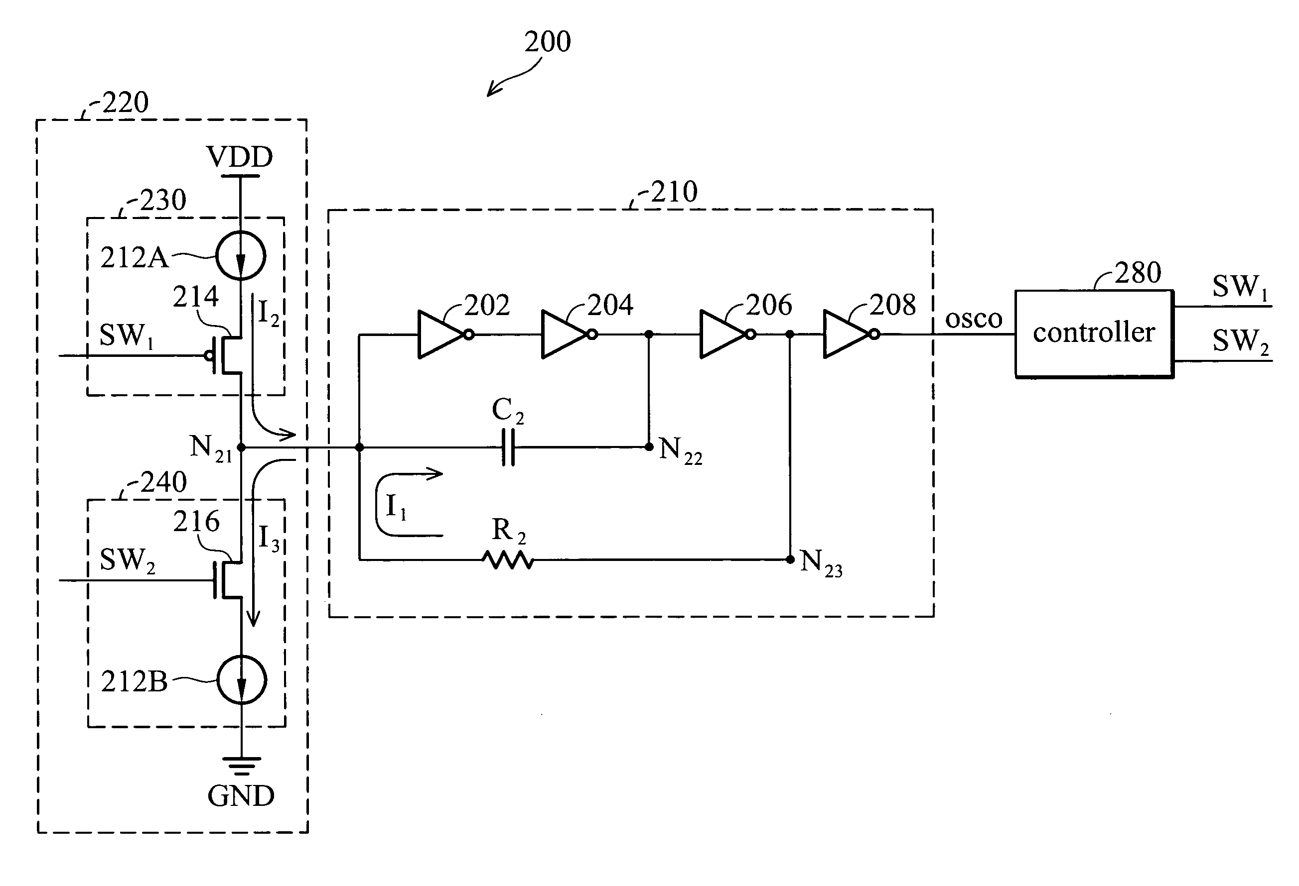
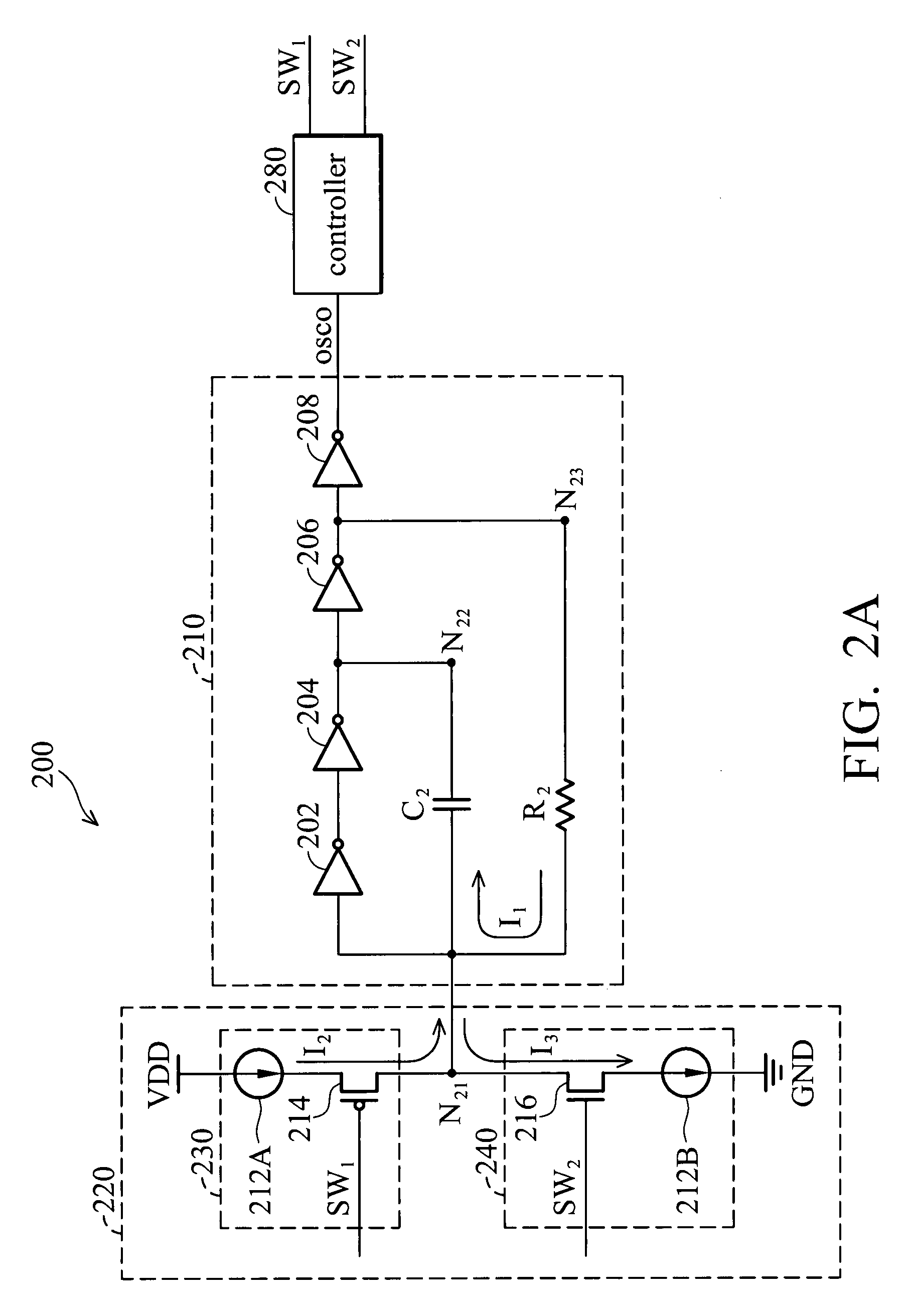
[0022]FIG. 2A is a schematic view of an RC oscillator 200 according to an embodiment of the invention. RC oscillator 200 comprises compensating circuit 220, oscillating module 210 and controller 280. Compensating circuit 220 comprises charging circuit 230 and discharging circuit 240.

[0023]Charging circuit 230 comprises first current source 212A and second transistor 214. First current source 212A is coupled between voltage source VDD and second transistor 214. Second transistor 214 has a second first terminal coupled to first current source 212A, a second second terminal coupled to first node N21, and a second gate for receiving first switching signal SW1.

[0024]Dischar...


PUM


Abstract

An oscillator comprising a compensation circuit, an oscillating module and a controller are disclosed. The compensation circuit comprises a charging circuit and a discharging circuit. The charging circuit comprises a first current source coupled between a voltage source and a second transistor, and the second transistor having a second first terminal coupled to a first current source, a second second terminal coupled to a first node, and a second gate for receiving a first switching signal. The discharging circuit comprises a third transistor having a third first terminal coupled to the first node and a third gate for receiving a second switching signal, and a second current source coupled between the third transistor and ground. The oscillating module couples between the compensation circuit and the controller and generates an output signal. The controller generates the first switching signal and the second switching signal according to the output signal.

Description

BACKGROUND OF THE INVENTION[0001]1. Field of the Invention[0002]The invention relates to an oscillator, and more particularly relates to an oscillator with low voltage, process variation and temperature sensitivity.[0003]2. Description of the Related Art[0004]FIG. 1 is a schematic view of a conventional RC oscillator 100. RC oscillator 100 comprises three inverters 102, 104 and 108, capacitor C1, resistor R1 and inverting unit 106.[0005]Inverter 102 has an input terminal coupled to node N11 and an output terminal. Inverter 104 has an input terminal coupled to the output terminal of inverter 102 and an output terminal coupled to node N12. Capacitor C1 is coupled between node N11 and node N12. Resistor R1 is coupled between node N11 and node N13. Inverting unit 106 is coupled between node N12 and node N13. Inverter 108 has an input terminal coupled to node N13 and an output terminal for generating an output signal 110.[0006]Inverting unit 106 can be an NAND gate or an inverter. In thi...

Claims


Application Information

Patent Timeline
Patent Type & Authority Applications(United States)
IPC IPC(8): H03K3/36
CPCH03K3/03H03K3/011
Inventor SHEEN, WEN-WANNCHAN, MING-HSIN
Owner PRINCETON TECHNOLOGY
Why Eureka
Try Eureka