Buffer member

a buffer member and member technology, applied in the field of buffer members, can solve the problems of unstable electrical connection, unstable electrical connection, and complicated incorporation of the hard disk drive into the accommodating portion, and achieve the effect of stable electrical connection

Inactive Publication Date: 2008-01-31
POLYMATECH CO LTD
View PDF18 Cites 26 Cited by
  • Summary
  • Abstract
  • Description
  • Claims
  • Application Information

AI Technical Summary

Benefits of technology

[0008]The present invention has been made in view of the above-mentioned problems in the prior art. It is accordingly an object of the present invention to provide a buffer member that helps to esta

Problems solved by technology

Such an information processing apparatus has a problem in that a malfunction occurs as the operational frequency increases due to electromagnetic wave noise, charging with static electricity, etc.
However, in the technique in which the conductive contact member is provided, the contact member of the accommodating portion and the casi

Method used


Image

  • Buffer member
  • Buffer member
  • Buffer member

Examples


example 1

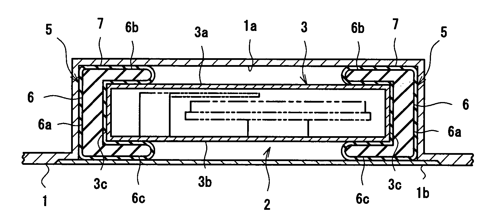
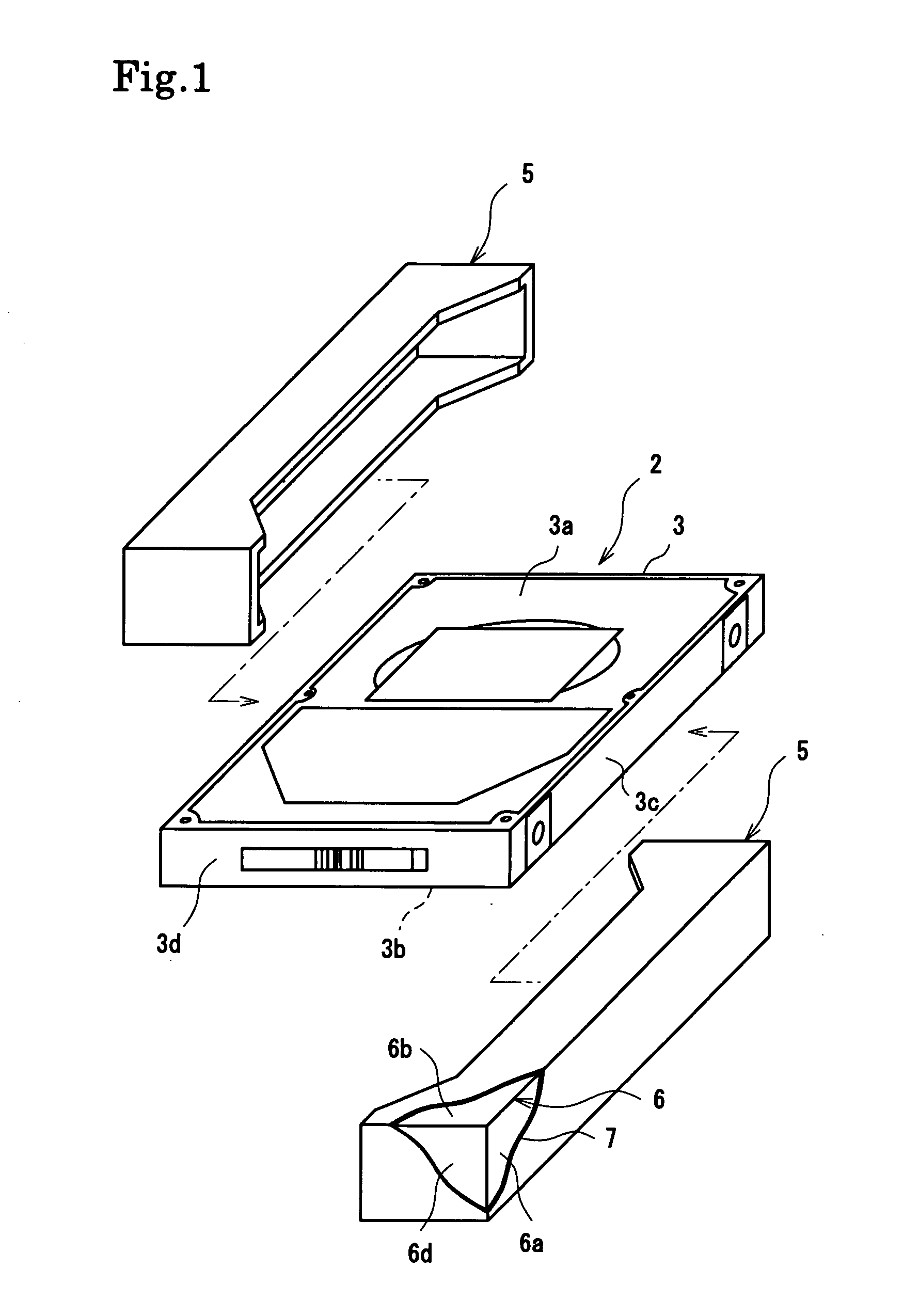
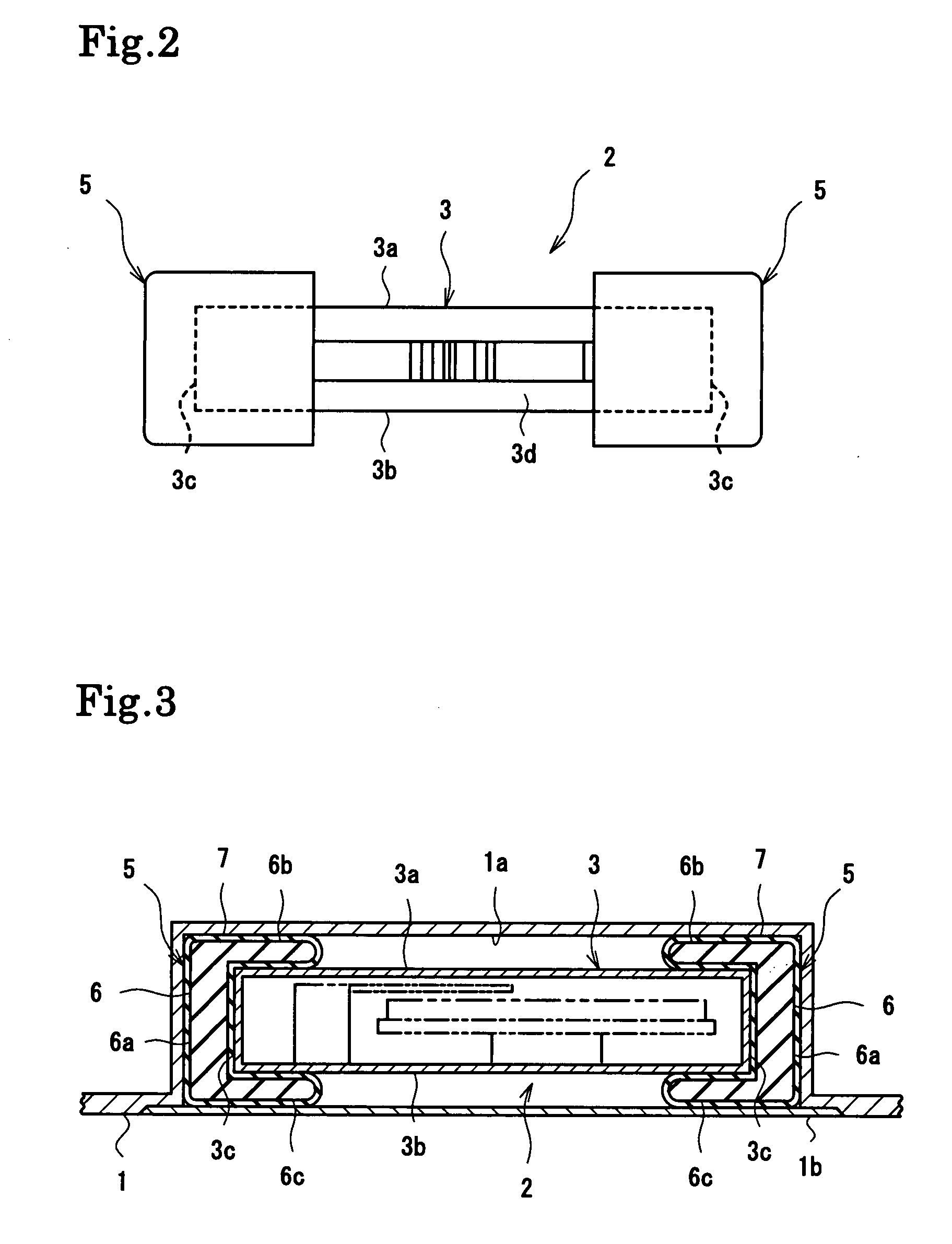
[0073]First, the buffer member main body 6 of styrene-based thermoplastic elastomer was formed by injection molding. The buffer member main body 6 is configured to have the side surface support portion 6a extending along the longitudinal side surface 3c of the casing 3 of the hard disk drive 2, the upper surface support portion 6b protruding from one end of the side surface support portion 6a to the upper surface 3a of the casing 3, and the bottom surface support portion 6c protruding likewise from the other end of the side surface support portion 6a to the bottom surface 3b, and exhibits a U-shaped sectional configuration. Further, at both longitudinal ends, there are provided the holding portions 6d bent so as to extend along the shorter side surfaces 3d of the casing 3 of the hard disk drive 2. Next, the buffer member main body 6 was dipped in a conductive coating material prepared by mixing a silver filler with a polyester resin used as the base material, and the conductive coat...

example 2

[0074]As in the case of the buffer member main body 6 of Example 1, the buffer member main body 9 was formed of a rubber-like elastic material composed of styrene-based thermoplastic elastomer, the buffer member main body 9 having the side surface support portion 9a, the upper surface support portion 9b, the bottom surface support portion 9c, and the holding portions 9d and exhibiting a U-shaped sectional configuration. In Example 2, however, the side surface support portion 9a has the five through-holes 9e extending through the thickness thereof. Next, as in Example 1, the buffer member main body 9 was dipped in the conductive coating material prepared by mixing a silver filler with a polyester resin used as the base material, and the conductive coating material was applied so as to cover the entire surface of the buffer member main body 9 including the hole wall surfaces of the through-holes 9e. After that, the conductive coating material applied was cured to form the conductive c...


PUM


Abstract

Provided is a buffer member helping to achieve stable electrical connection between a casing of an external storage device and an accommodating portion thereof without involving an increase in the number of components. A buffer member has a conductive connection layer held in contact with a hard disk drive and with an accommodating portion, so it is possible to dissipate static electricity with which the hard disk drive is charged and electromagnetic wave noise through the conductive connection layer to the accommodating portion or a casing of a notebook PC electrically continuous with the accommodating portion. Thus, it is possible to prevent malfunction of the hard disk drive and to correctly operate the notebook PC. Further, there is no need to separately provide a conductive member for conductive connection between the hard disk drive and the accommodating portion, thereby making it possible to avoid an increase in the number of components. Thus, the hard disk drive can be easily incorporated into the accommodating portion.

Description

BACKGROUND OF THE INVENTION[0001]1. Field of the Invention[0002]The present invention relates to a buffer member which protects from a shock, vibration, etc. an external storage device such as a hard disk drive accommodated in an information processing apparatus including a notebook type personal computer, a car audio apparatus, a car navigation apparatus, a portable audio player, or a digital video camera.[0003]2. Description of the Related Art[0004]As shown in FIG. 10, a hard disk drive 2 serving as an external storage device accommodating a disk-shaped storage medium is accommodated in an accommodating portion 1a of a notebook type personal computer (hereinafter referred to as “notebook PC”) serving as an information processing apparatus. As disclosed in JP 2005-38538 A, the hard disk drive 2 is, for example, provided with a box-shaped casing 3 with an upper surface 3a and a bottom surface 3b that are substantially rectangular, with buffer members 4 formed of a soft rubber-like e...

Claims


Application Information

Patent Timeline
IPC IPC(8): G06F1/16
CPCG06F1/184G06F1/187G11B33/1493G11B33/124G11B33/08
Inventor YAMAGUCHI, KENJI
Owner POLYMATECH CO LTD
Why Eureka
Try Eureka