Power tool equipped with light
- Summary
- Abstract
- Description
- Claims
- Application Information
AI Technical Summary
Benefits of technology
Problems solved by technology
Method used
Image

Examples
first embodiment
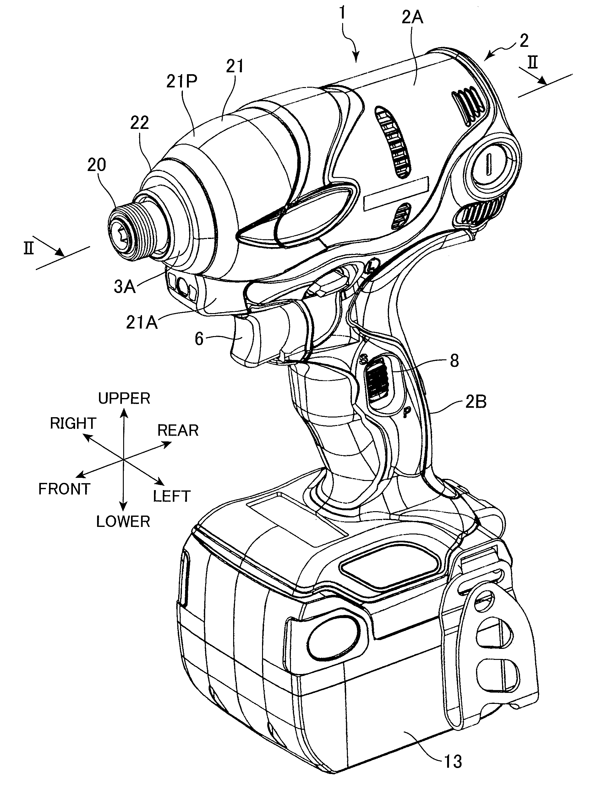
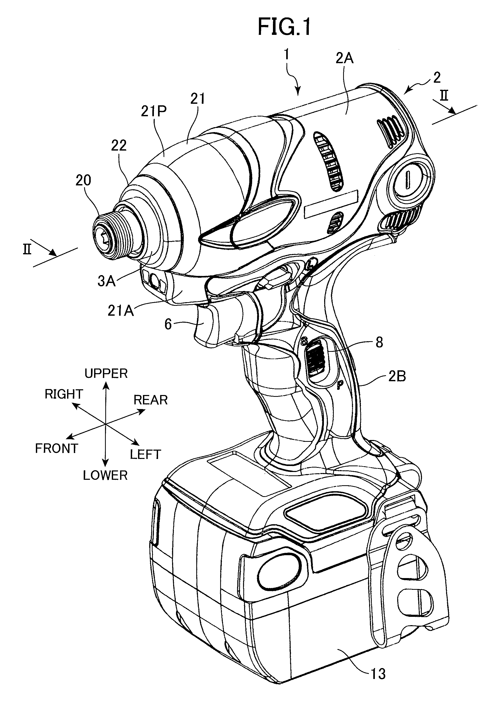
[0033]A power tool according to a first embodiment of the present invention will be described while referring FIGS. 1 through 12. In the following description and the drawings, the expressions “front”, “rear”, “upper”, “lower”, “right”, and “left” are used only for description purposes.
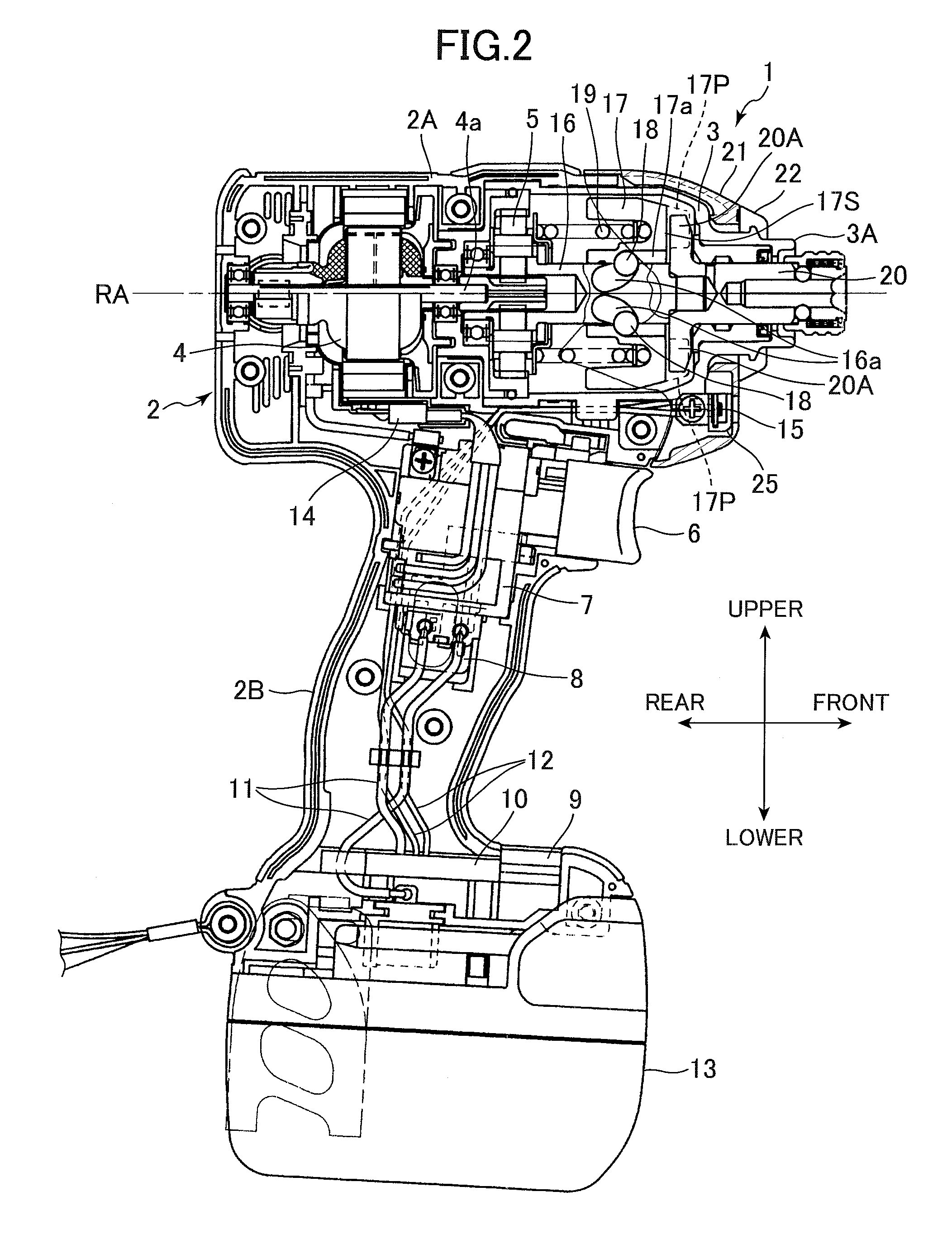
[0034]First, the basic structure and operations of an impact driver 1 as an example of the power tool will be described with reference to FIGS. 1 through 3. As shown in the drawings, the impact driver 1 has a housing 2 and a hammer case 3 constituting an outer frame of the impact driver 1. The housing 2 includes a main body 2A substantially cylindrical in shape and extending in the front-to-rear direction, and a handle part 2B joined with the main body 2A to form a substantially T-shape in a side view. The hammer case 3 is substantially cylindrical in shape and formed of an aluminum alloy. The hammer case 3 is provided at the front end of the housing 2.
[0035]As shown in FIGS. 1 and 2, a guide sleeve 3...
second embodiment
[0056]A power tool according to a second embodiment of the invention will be described while referring to FIGS. 10 through 12, wherein like parts and components are designated by the same reference numerals to avoid duplicating description.
[0057]In the second embodiment, the holder member 25 retaining the base plate 23 and LED 24 is attached to the hammer case 3 by fitting the holder member 25 onto the rib 3B of the hammer case 3. First, by simply fitting the rib 3B between the leg parts 25B and 25C of the holder member 25 shown in FIG. 12, the holder member 25 can be easily mounted on the rib 3B in one step, as shown in FIG. 11. In other words, a faster such as screw is not used in the present embodiment.
[0058]After the holder member 25 is mounted on the rib 3B as described above, the protector 21 shown in FIG. 10 covers and retains the holder member 25. Specifically, a lower rib-shaped guide 21B is integrally formed in the pouch member 21A, protruding upward from the inside lower ...
third embodiment
[0061]A power tool according to a third embodiment of the invention will be described while referring to FIGS. 13 through 19, wherein like parts and components are designated by the same reference numerals to avoid duplicating description.
[0062]FIG. 13 shows an impact driver 51 according to the third embodiment. As shown in FIG. 13, the impact driver 51 includes a main housing 52 substantially cylindrical in shape and extending in a front-rear direction along a rotational axis X of a DC motor 54; a handle housing 53 joined with the main housing 52 and extending in a vertical Y-direction orthogonal to the extending direction of the main housing 52 (X-direction) or a Z-direction at a certain angle θ from the Y-direction; and a hammer case 64 that is bell-shaped and accommodates an impact mechanism. The main housing 52 is coupled to the hammer case 64 by screws (not shown). A battery pack housing section (not shown) is provided in a lower end portion of the handle housing 53, and a bat...
PUM
| Property | Measurement | Unit |
|---|---|---|
| Diameter | aaaaa | aaaaa |
| Elasticity | aaaaa | aaaaa |
Abstract
Description
Claims
Application Information
 - Generate Ideas
- Intellectual Property
- Life Sciences
- Materials
- Tech Scout
- Unparalleled Data Quality
- Higher Quality Content
- 60% Fewer Hallucinations
Browse by: Latest US Patents, China's latest patents, Technical Efficacy Thesaurus, Application Domain, Technology Topic, Popular Technical Reports.
© 2025 PatSnap. All rights reserved.Legal|Privacy policy|Modern Slavery Act Transparency Statement|Sitemap|About US| Contact US: help@patsnap.com