
Communication load reducing method and computer system

a technology of communication load and computer system, applied in the field of computer system, can solve the problems of excessive broadcasting, inability to process broadcast packets in the nic, and useless use of computer resources, so as to reduce communication load and communication load

Inactive Publication Date: 2008-01-31
NEC CORP
View PDF7 Cites 44 Cited by
  • Summary
  • Abstract
  • Description
  • Claims
  • Application Information

AI Technical Summary

Benefits of technology

[0028]It is therefore an exemplary object of the present invention to provide a computer system in which generation of frames for a processing request can be suppressed under a virtual machine (VM) environment.
[0033]In another exemplary aspect of the present invention, a method of reducing a communication load, includes acquiring a frame and confirming whether or not the frame is a predetermined message; confirming whether or not address data of a server has been stored as an access destination address when the frame is the predetermined message; rewriting a destination address of the frame by the address data of the server when the address data of the server is stored; and starting an access destination registration requesting process when the address data of the server has not been stored as the access destination address.

Problems solved by technology

When the DHCP server is provided on a same machine (hyper-visor) as an integrated client by using one virtual machine, it is wasteful in a network band to broadcast a DHCP request from the client of the virtual machine on the same hyper-visor.
The above broadcast imposes a heavy load on a local area network.
However, a broadcast packet cannot be processed in the NIC, and is sent to a higher hierarchy.
Thus, a computer resource is uselessly used.
Such problems become remarkable in a virtual machine in which generations and removals are frequently executed.
Therefore, the broadcast executed by the virtual machine that is generated and started with a delay on the host is redundant.
Thus, there is a case that the heavy load is imposed on a particular DHCP server.
However, all of the above-mentioned related arts do not disclose a device for suppressing broadcast.

Method used


Image

  • Communication load reducing method and computer system
  • Communication load reducing method and computer system
  • Communication load reducing method and computer system

Examples


first exemplary embodiment

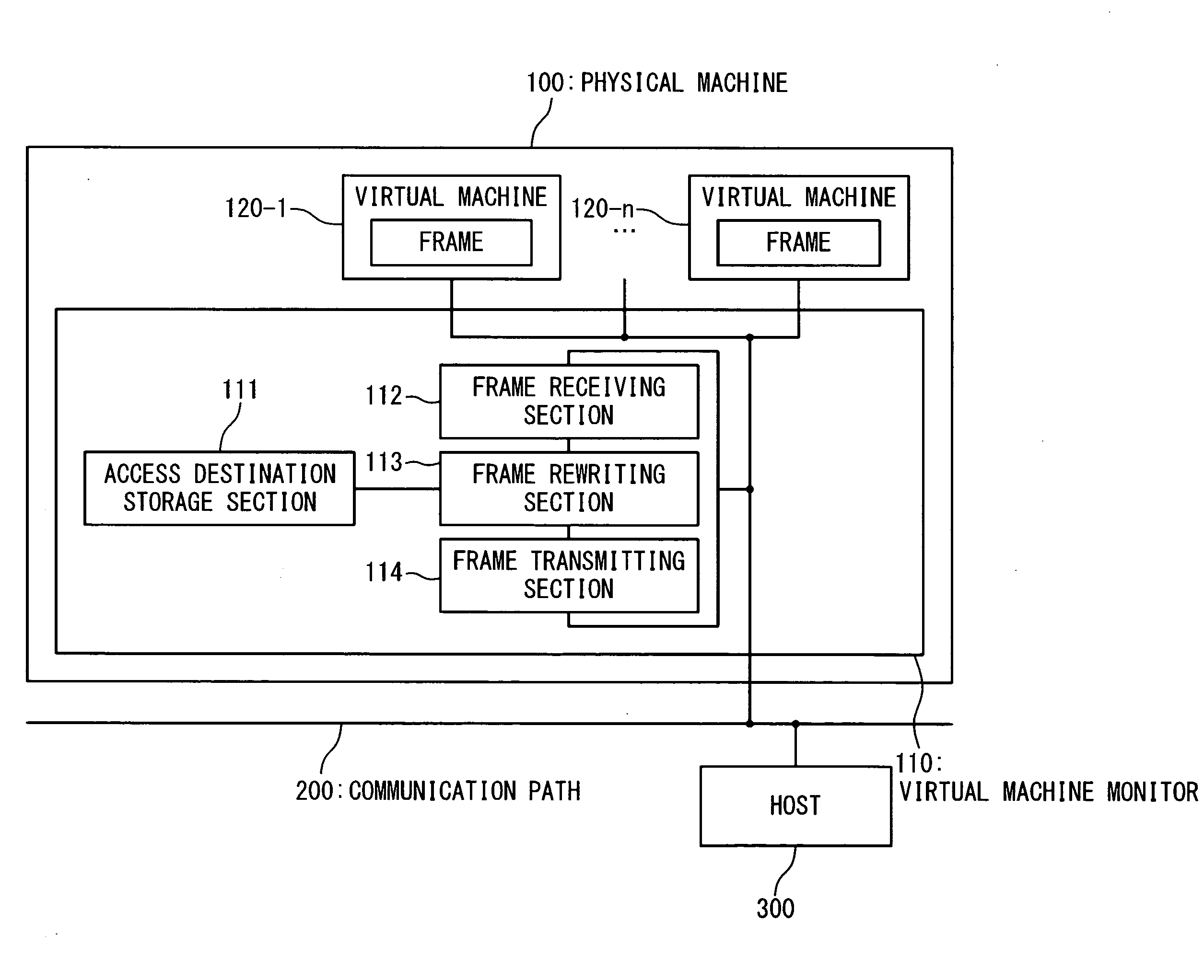
[0057]FIG. 4 is a block diagram showing a configuration of the computer system according to a first exemplary embodiment of the present invention. With reference to FIG. 4, the computer system according to the first exemplary embodiment of the present invention contains a physical machine 100, a communication path 200 and a host 300. The physical machine 100 contains a virtual machine monitor 110 and virtual machines 120 (120-k, k=1 to n: n is the number of the virtual machines). The virtual machine monitor 110 and the virtual machine 120 operate on the physical machine 100. The virtual machine monitor 110 may be a configuration referred to as VMM (Virtual Machine Monitor) or a hyper-visor. The virtual machine 120 is VM (Virtual Machine) that is generated and started by the physical machine 100. The communication path 200 is a network for supporting a broadcast communication such as Ethernet (Registered Trademark).

[0058]It should be noted that the virtual machine monitor 110 and the...

second exemplary embodiment

[0080]The configuration of the computer system according to a second exemplary embodiment of the present invention will be described below in detail with reference to the drawings. With reference to FIG. 11, in the configuration of the computer system according to the second exemplary embodiment of the present invention, a plurality of access destination server addresses can be stored as the access destination storage section 111 of FIG. 4.

[0081]The operations of the computer system according to the second exemplary embodiment of the present invention will be described below in detail with reference to a flowchart of FIG. 12. In FIG. 12, steps S106 to S108 are added to the flowchart of FIG. 8. However, the other steps are same as those of FIG. 8.

(1) Step S101

[0082]When a frame transmitted from the virtual machine 120-1 is received by the frame receiving section 112, whether or not the frame is the broadcast frame is checked. This check is carried out by determining whether or not th...

third exemplary embodiment

[0091]The configuration of the computer system according to a third exemplary embodiment of the present invention will be described below in detail with reference to the drawings. With reference to FIG. 13, the access destination storage section 111 records the address data of the DHCP server together with its storage time when it is stored. With reference to FIG. 14, the frame rewriting section 113 in the third exemplary embodiment executes a step S109 added to the flowchart of FIG. 8.

(1) Step S101

[0092]When the frame transmitted from the virtual machine 120-1 is received by the frame receiving section 112, whether or not the frame is the broadcast frame is checked. This check is carried out by determining whether or not the destination address is the broadcast address in the DHCP message format shown in FIG. 9.

(2) Step S102

[0093]If this frame is the broadcast frame, the frame rewriting section 113 checks whether or not this frame serves as the DHCP message.

(3) Step S109

[0094]Even ...


PUM


Abstract

A computer system connected to a network includes a terminal apparatus configured to detect an access destination on the network, acquire a destination data of the access destination, and generate a frame having the destination data for the access destination; and a monitoring apparatus configured to hold the destination data, and to produce at least one unicast frame to the access destination based on the destination data of the frame received from the terminal apparatus. The monitoring apparatus issues an access destination registration request to the terminal apparatus, and acquires the destination data from the terminal apparatus. The terminal apparatus holds a data indicative of reception of the access destination registration request from the monitor apparatus and notifies the destination data to the monitoring apparatus if the data indicative of the reception of the access destination registration request is stored when receiving a reply from the access destination.

Description

TECHNICAL FIELD[0001]The present invention relates to a computer system, and more particularly relates to a technique for suppressing transmission of a frame from a terminal in a computer system.BACKGROUND ART[0002]In an environment in which virtual machines (VMs) are used to integrate a plurality of clients, an IP address is considered to be set by using a service of a DHCP (Dynamic Host Configuration Protocol) system as one of client server systems in many cases. A virtual NIC (Network Interface Card) is assigned to each client, and this is connected through a physical NIC to LAN.[0003]When the DHCP server is provided on a same machine (hyper-visor) as an integrated client by using one virtual machine, it is wasteful in a network band to broadcast a DHCP request from the client of the virtual machine on the same hyper-visor. Also, there is a possibility that the DHCP server in this case is used from other than the hyper-visor environment, or the client of the virtual machine on th...

Claims


Application Information

Patent Timeline
Patent Type & Authority Applications(United States)
IPC IPC(8): G06F15/173G06F15/16
CPCH04L29/12028H04L29/12339H04L61/2503H04L61/2015H04L61/103H04L61/5014
Inventor MIYAJIMA, HIROAKI
Owner NEC CORP
Learn More