State Detection Device
a detection device and state technology, applied in the direction of mechanical measurement arrangement, mechanical roughness/irregularity measurement, instruments, etc., can solve the problems of not accurately extracting potential, nor measuring flow rate with precision
- Summary
- Abstract
- Description
- Claims
- Application Information
AI Technical Summary
Benefits of technology
Problems solved by technology
Method used
Image
Examples
first embodiment
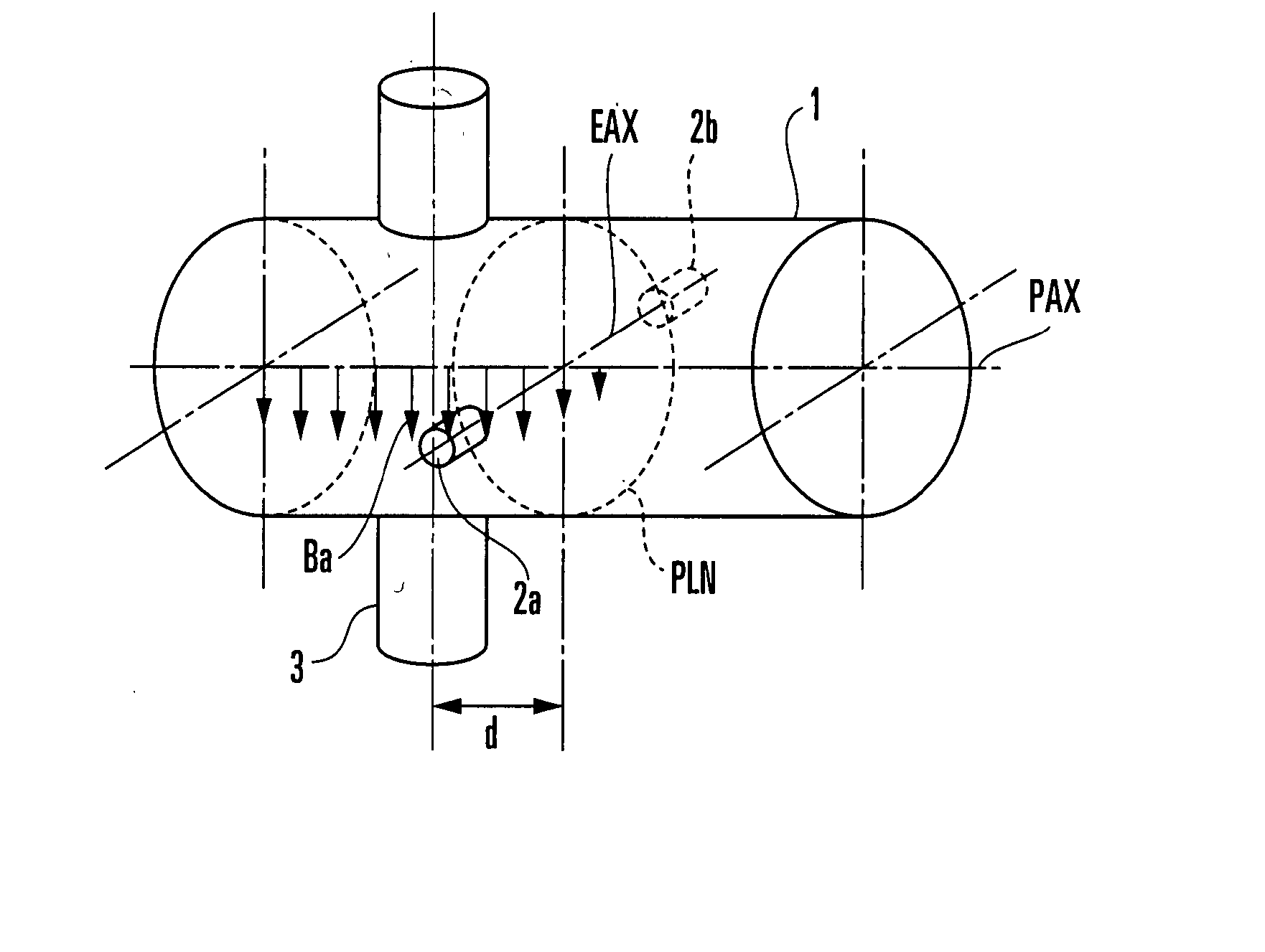
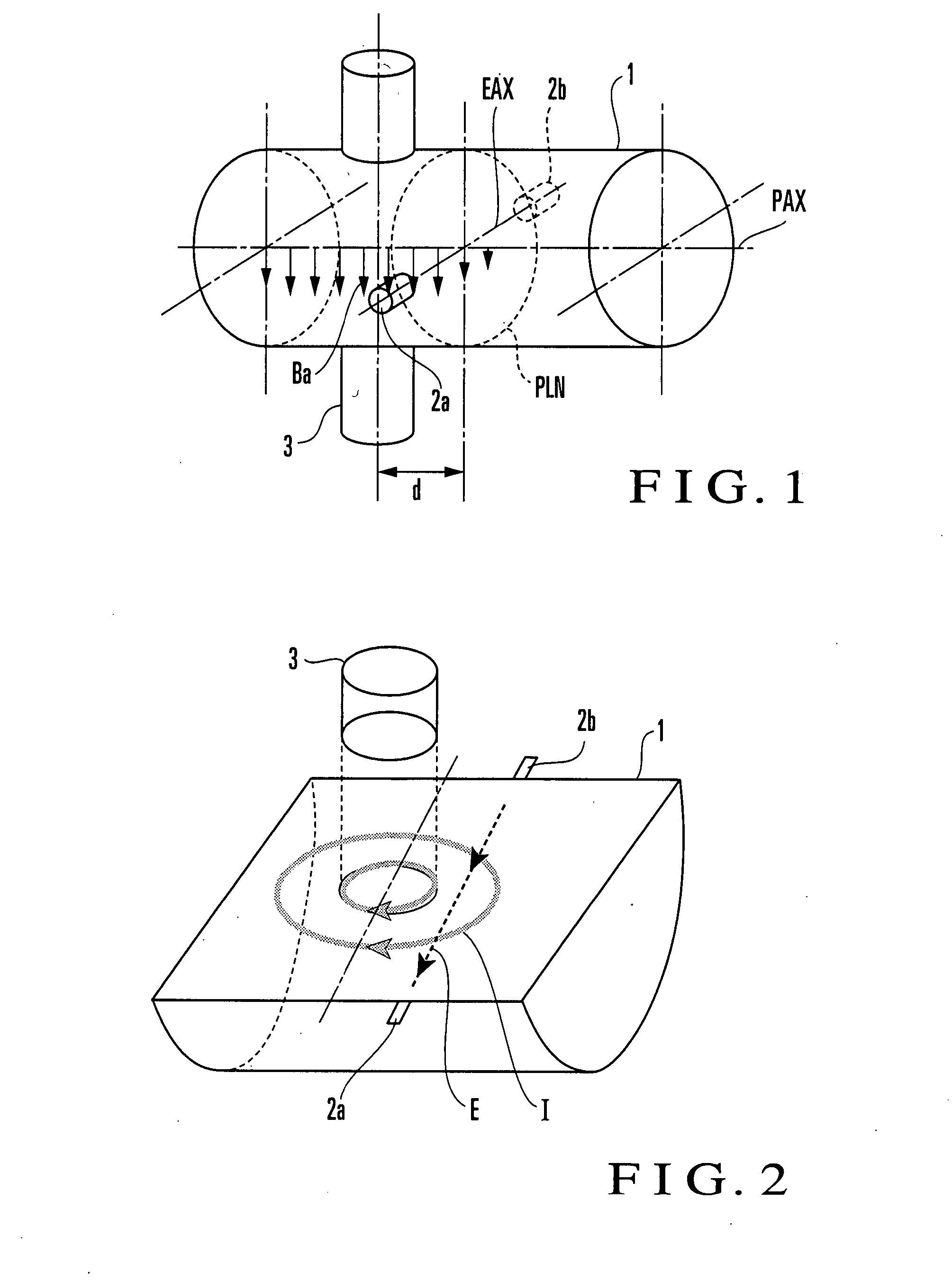
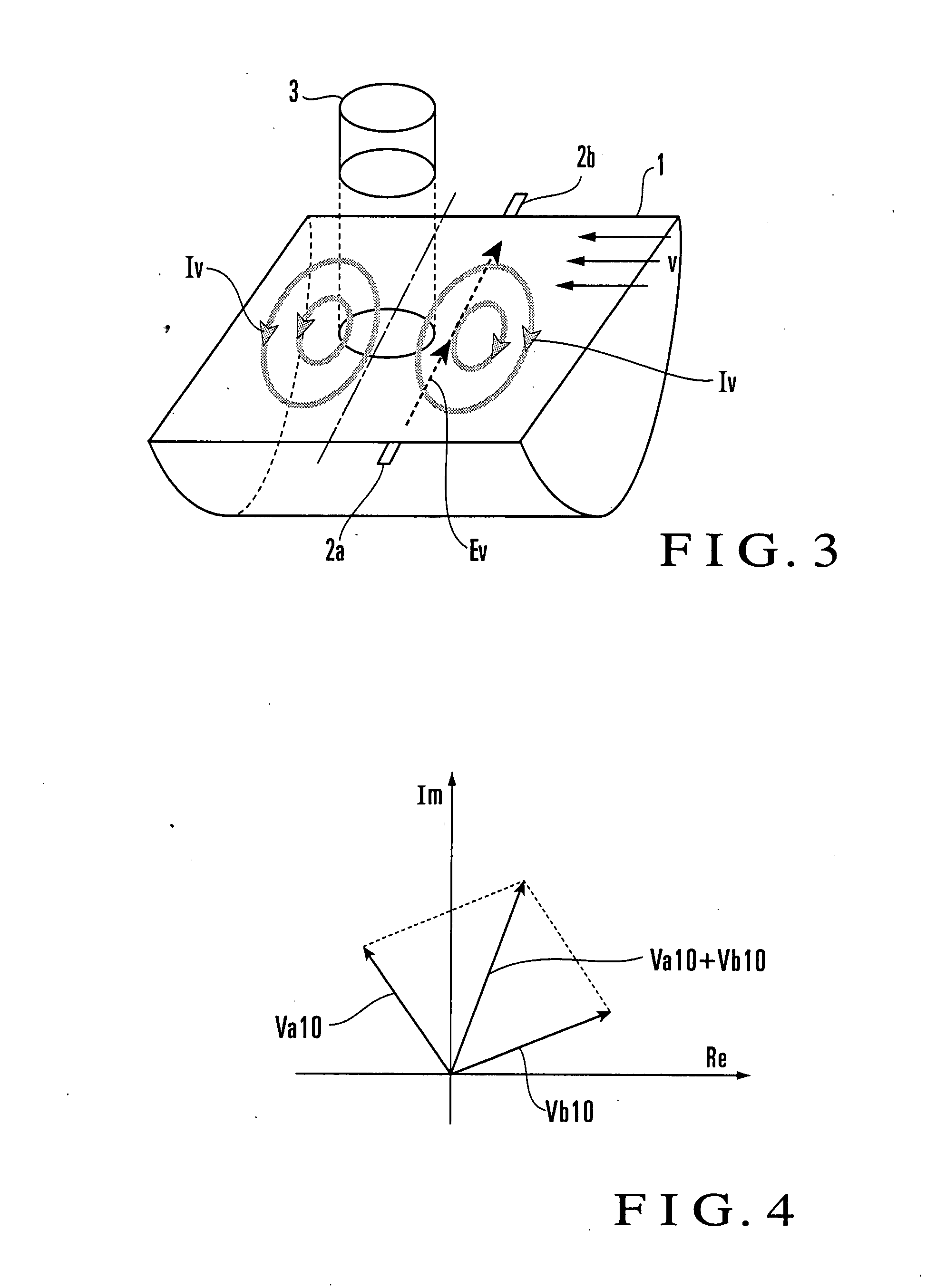
[0200] The first embodiment of the present invention will be described in detail next. This embodiment uses the first principle described above. A state detection device according to this embodiment includes one exciting coil and a pair of electrodes, and has the same arrangement as that of the state detection device shown in FIG. 1 except for the signal processing system. The principle of this embodiment will therefore be described by using reference numerals in FIG. 1. This embodiment uses the first extraction method as a method of extracting a ∂A / ∂t component from a resultant vector, and obtains the first parameter irrelevant to an exciting frequency. An example of the first parameter is the level of a fluid or the deposited state of a substance adhering to the inside of a measuring tube.
[0201] When an exciting current with an angular frequency ω0 is supplied to an exciting coil 3, and the first parameter is p1, an inter-electrode electromotive force E110 is represented by the f...
second embodiment
[0228] The second embodiment of the present invention will be described next. This embodiment is the same as the first embodiment except that one exciting coil is added to the state detection device, and uses the above-described second principle. That is, the state detection device of this embodiment includes two exciting coils and a pair of electrodes, and has the same arrangement as that of the state detection device shown in FIG. 5 except for the signal processing system. The principle of this embodiment will therefore be described by using reference numerals in FIG. 5. If the second exciting coil to be newly added is placed on the same side as the first exciting coil, the resultant arrangement is a redundant arrangement of the first embodiment. Therefore, the second exciting coil needs to be placed on a side different from that of the first exciting coil through a plane including the electrodes. This embodiment uses the first extraction method as a method of extracting a ∂A / ∂t c...
third embodiment
[0259] The third embodiment of the present invention will be described next. A state detection device according to this embodiment includes two exciting coils and a pair of electrodes, and has the same arrangement as that of the state detection device shown in FIG. 5 except for the signal processing system. The principle of this embodiment will therefore be described by using reference numerals in FIG. 5. This embodiment uses the second extraction method as a method of extracting a ∂A / ∂t component from a resultant vector to obtain the first parameter irrelevant to an exciting frequency.
[0260] Assume that the first exciting current having an angular frequency ω0 is supplied to a first exciting coil 3a, the second exciting current having the angular frequency ω0 with a phase difference Δθ2+π with respect to the first exciting current is supplied to a second exciting coil 3b, and the first parameter is p3. In this case, an inter-electrode electromotive force E320R is represented by th...
PUM
 Abstract
Description
Claims
Application Information
 - R&D
- Intellectual Property
- Life Sciences
- Materials
- Tech Scout
- Unparalleled Data Quality
- Higher Quality Content
- 60% Fewer Hallucinations
Browse by: Latest US Patents, China's latest patents, Technical Efficacy Thesaurus, Application Domain, Technology Topic, Popular Technical Reports.
© 2025 PatSnap. All rights reserved.Legal|Privacy policy|Modern Slavery Act Transparency Statement|Sitemap|About US| Contact US: help@patsnap.com


