Method and apparatus for arranging a solar cell and reflector

a solar cell and reflector technology, applied in lighting and heating equipment, light radiation electric generators, generators/motors, etc., can solve the problems of high cost of solar devices, especially solar photovoltaic cells, and the use of solar energy, and achieve the effect of reducing performan

Inactive Publication Date: 2008-02-07
SIMON DANIEL
View PDF63 Cites 37 Cited by
  • Summary
  • Abstract
  • Description
  • Claims
  • Application Information

AI Technical Summary

Benefits of technology

[0010]1. A simple arrangement that allows either more sunlight to be captured with the same area of solar cell, or the same amount of sunlight can be captured with a smaller solar cell.
[0011]2. Most prior art practices of module making remain the same with the present invention, with the exception that a deeper module / enclosure is needed, as well as a way to support the reflector and solar cell in their new orientation. The wiring or plumbing that was typically built along the back surface of the solar cell, or row of solar cells, is generally unaffected by the new orientation.
[0012]3. The reflector and cell arrangement of the present invention are protected from the elements and it can be used with many types of solar cell technologies and will uniformly illuminate the solar cell surface.
[0013]4. The reflector can be designed to reflect only the solar spectrum that generates electricity (for a PV solar cell) but not the infrared parts that might overheat the cell and reduce performance.
[0014]Further objects and advantages of my invention will become apparent from a consideration of the drawings and ensuing description.

Problems solved by technology

One of the main obstacles to widespread use of solar energy is the high cost of solar devices, especially solar photovoltaic cells.
This is because of the relatively high cost of materials used to convert solar energy (especially relative to reflector material).
Much of the prior art assumes the solar cells are arranged in a single plane normal to the incoming sunlight and parallel to the transparent cover, such as: U.S. Pat. Nos. 6,528,716 and 4,316,448 Disadvantages of these types of arrangements primarily include the inefficient or wasteful use of expensive materials.
Disadvantages of these types of arrangements are complex geometries or the requirement of mechanical tracking systems which add to the cost of system manufacture and maintenance.
Espy teaches a complex and variable geometry that depends on user location, which makes mass production difficult.
Furthermore, the arrangement described by Espy does not contain protection for the reflector or collector surfaces.
The result is that one or both of these surfaces can be easily damaged by the elements.

Method used


Image

  • Method and apparatus for arranging a solar cell and reflector
  • Method and apparatus for arranging a solar cell and reflector
  • Method and apparatus for arranging a solar cell and reflector

Examples


Embodiment Construction

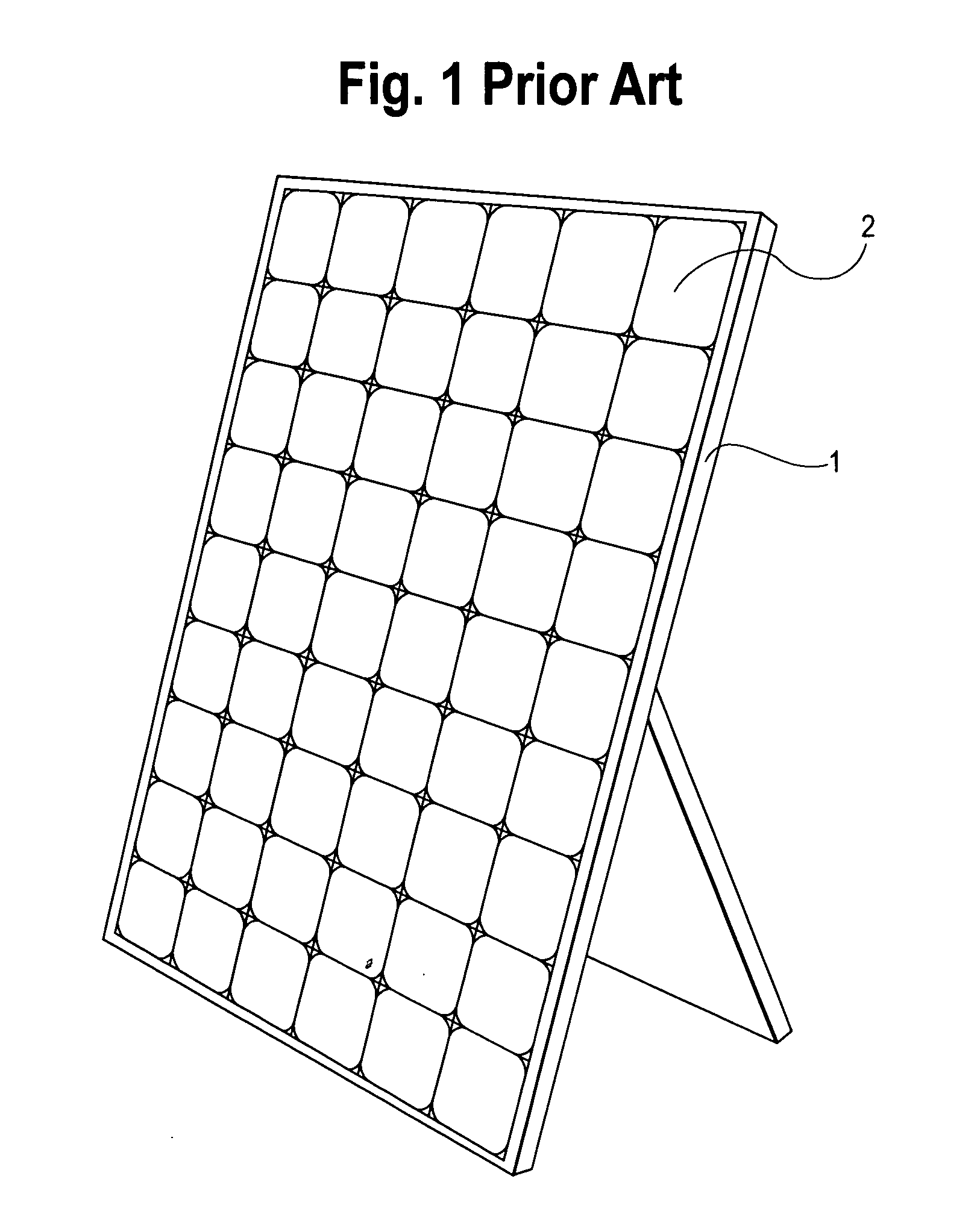
[0023]FIG. 1 shows a prior art method of making a solar panel. A frame 1 is built and either supported or attached to a roof with flat, tiled panels 2 that contain solar cells. Tiles may have weather-tight covers to protect the cells. This arrangement does not lead to optimum efficiency in the amount of light striking the cells.

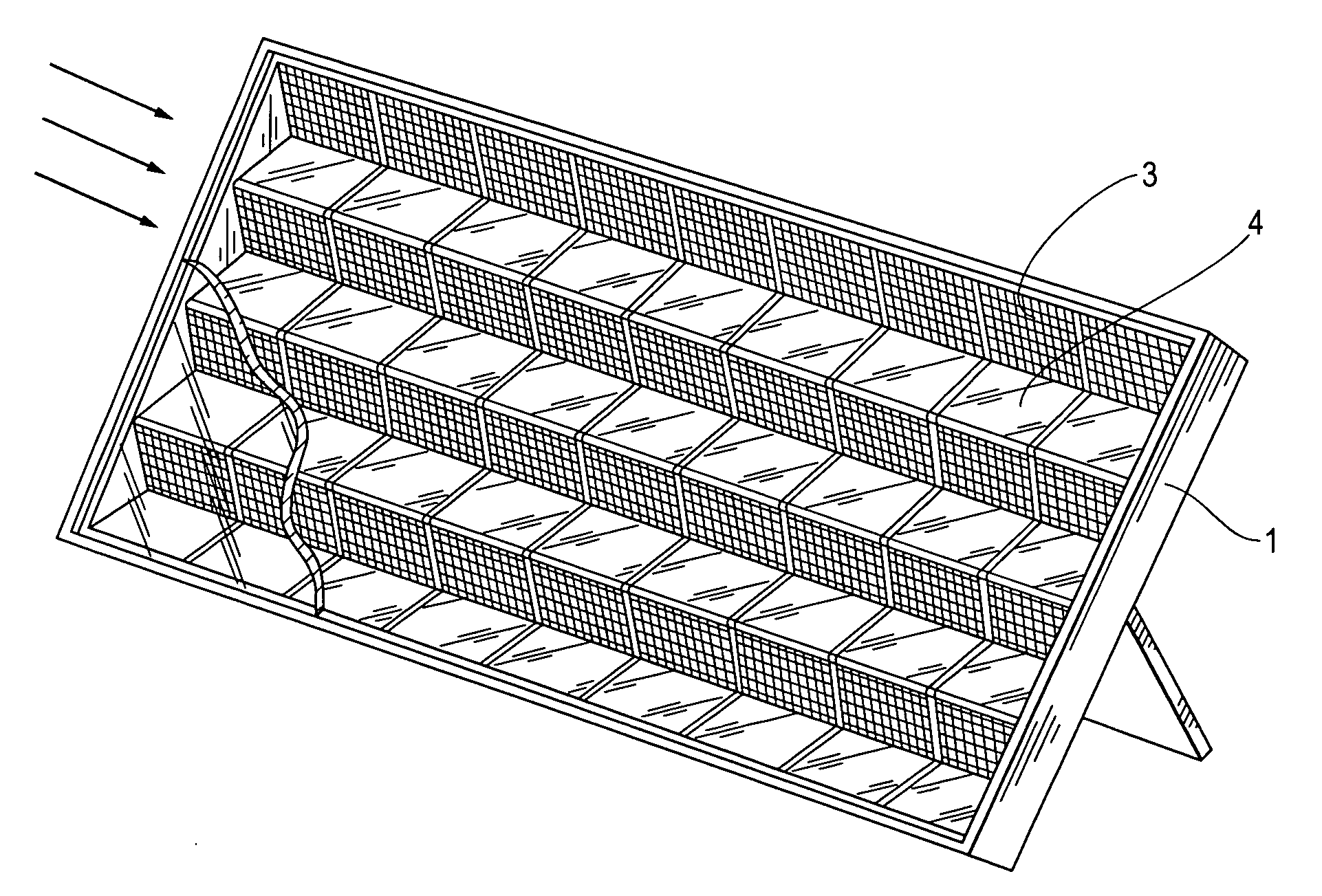
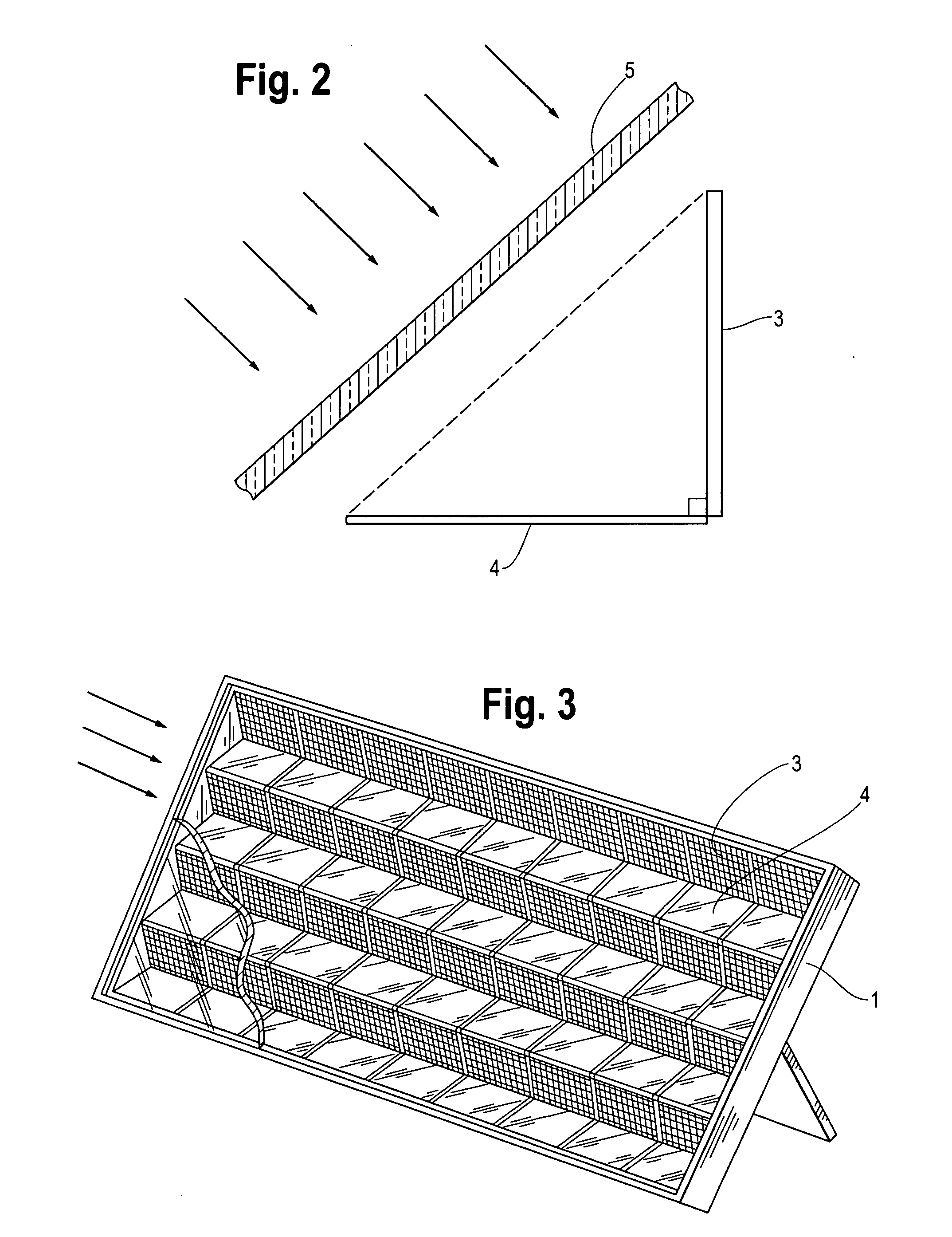
[0024]FIG. 2 shows a side view of an embodiment of the present invention. A solar cell 3 is rotated at around a 45 degree angle to module cover 5. A reflector 4, also at around a 45 degree angle to module cover 5 is located approximately perpendicular to and adjacent to solar cell 3. The reflector 4 can be equivalent in length and width to solar cell 3. The reflector 4 and solar cell 3 form a V-shape with the opening parallel to module cover 5. Light that enters the module perpendicular to the module cover 5 will hit the solar cell 3 (at a 45 degree angle) directly or after reflecting off reflector 4. The solar cell 3 combined with the reflector 4 in this ori...


PUM


Abstract

A system and method of arranging a solar cell and reflector to replace a typical solar cell oriented normal to the incoming sunlight inside a module (i.e. parallel to a module's transparent cover plate or opening). The present invention in a preferred embodiment uses a solar cell oriented at a 45 degree angle to the incoming sunlight, and a reflective surface oriented perpendicular to the cell and at a 45 degree angle to the incoming sunlight. The solar cell and the mirror are the same length/size and form a V shape where the angle between the sloped sides is 90 degrees. Any light falling normally on the arrangement will hit the solar cell either directly or after reflection. In another embodiment, two adjacent reflectors can be used making angles of around 60 degrees and around 30 degrees with respect to the cover or opening. An alternate embodiment can include a second reflector added to the base of the cell and reflector pairings also at an approximate 45 degree angle with the cover or opening. The second reflector can run along an entire row of cell and first reflector pairs such that the first reflectors form 90 degree angles with both the cells and with the second reflector.

Description

BACKGROUND[0001]1. Field of Invention[0002]This invention relates generally to solar panels and more specifically to an improved arrangement of a solar cell and reflector in a module or panel.[0003]2. Description of the Prior Art[0004]There is a significant interest in the commercial application of solar energy. One of the main obstacles to widespread use of solar energy is the high cost of solar devices, especially solar photovoltaic cells. This is because of the relatively high cost of materials used to convert solar energy (especially relative to reflector material). It is well known in the art to use a solar cell for intercepting sunlight and producing energy of thermal or electrical nature (or a combination of both). A solar cell generally can mean a receiver or thermal absorbing plate (for solar thermal applications) or a solar photovoltaic cell (for solar electrical applications). Cells are frequently connected or joined to other cells either in parallel or in series within a...

Claims


Application Information

Patent Timeline
Patent Type & Authority Applications(United States)
IPC IPC(8): H02N6/00F24S23/70
CPCH01L31/0547Y02E10/52
Inventor SIMON, DANIEL
Owner SIMON DANIEL
Why Eureka
Try Eureka