Particle-matrix composite drill bits with hardfacing and methods of manufacturing and repairing such drill bits using hardfacing materials

a technology of composite drill bits and hardfacing materials, which is applied in the field of particle-matrix composite drill bits, can solve the problems of complex and labor-intensive fabrication processes, inability to meet the needs of drilling, and inability to use drill bits b>10/b>, and achieve the effect of enhancing the surface wear resistan

Inactive Publication Date: 2008-02-07
BAKER HUGHES INC
View PDF69 Cites 91 Cited by
  • Summary
  • Abstract
  • Description
  • Claims
  • Application Information

AI Technical Summary

Benefits of technology

[0018] A rotary drill bit is provided that provides a particle-matrix composite material devoid of a molten binder or infiltrant material as is conventionally employed in so-called “matrix”-type drill bits. Such a drill bit may also be characterized as having a “sintered” particle-matrix composite structure. Further, the rotary drill bit includes an abrasive, wear-resistant material, which may be characterized as a “hardfacing” material, for enhancing the wear-resistance of surfaces of the drill bit.

Problems solved by technology

Advantageously, a particle-matrix composite material provides a bit body of higher strength and toughness compared to steel material, but still requires complex and labor-intensive processes for fabrication, as described in U.S. application Ser. No. 11 / 272,439.
Eventually, the surfaces of the bit body 12 may wear to an extent at which the drill bit 10 is no longer suitable for use.
Also, the cutting elements 22 may wear to an extent at which they are no longer suitable for use.
During use, small vugs, voids and other defects may be formed in exposed surfaces of the bonding material 24 due to wear.
Solids-laden drilling fluids and formation debris generated during the drilling process may further erode, abrade and enlarge the small vugs and voids in the bonding material 24.
Loss of a cutting element 22 during a drilling operation can lead to rapid wear of other cutting elements and catastrophic failure of the entire drill bit 10.
Ideally, the materials of a rotary drill bit must be extremely hard to withstand abrasion and erosion attendant to drilling earth formations without excessive wear.
In practicality, however, materials that exhibit extremely high hardness tend to be relatively brittle and do not exhibit high fracture toughness, while materials exhibiting high fracture toughness tend to be relatively soft and do not exhibit high hardness.

Method used


Image

  • Particle-matrix composite drill bits with hardfacing and methods of manufacturing and repairing such drill bits using hardfacing materials
  • Particle-matrix composite drill bits with hardfacing and methods of manufacturing and repairing such drill bits using hardfacing materials
  • Particle-matrix composite drill bits with hardfacing and methods of manufacturing and repairing such drill bits using hardfacing materials

Examples


Embodiment Construction

[0048] The illustrations presented herein are, in some instances, not actual views of any particular drill bit, cutting element, hardfacing material or other feature of a drill bit, but are merely idealized representations which are employed to describe the present invention. Additionally, like elements and features among the various drawing figures are identified for convenience with the same or similar reference numerals.

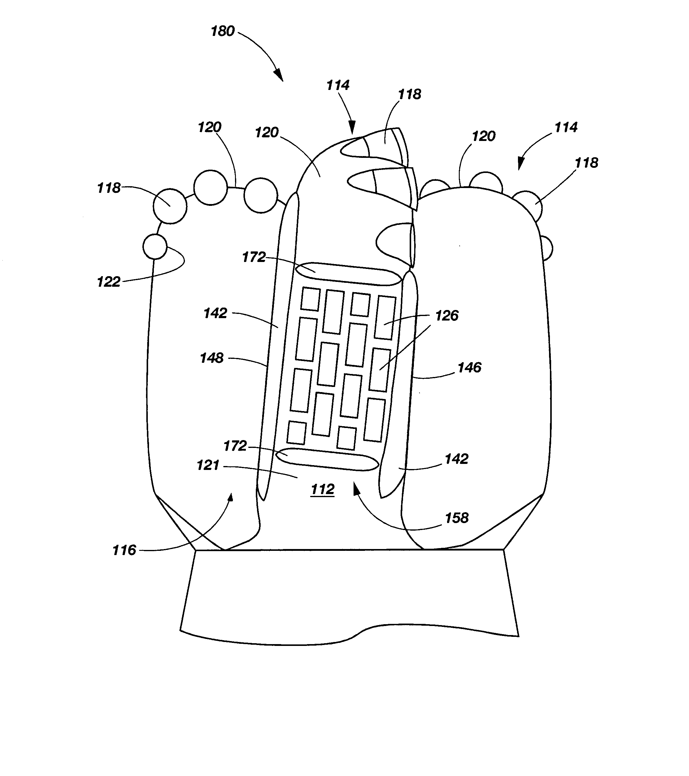
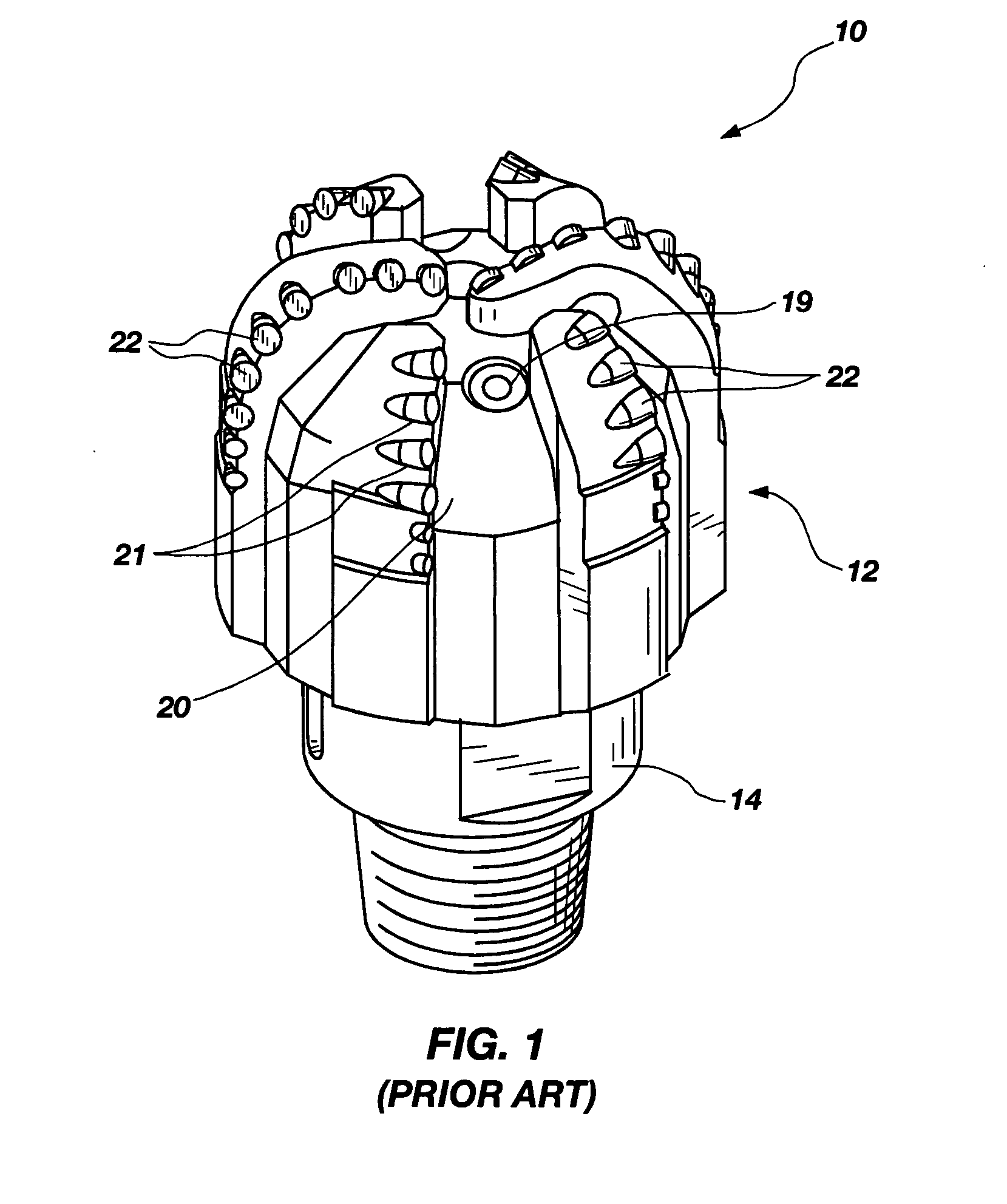
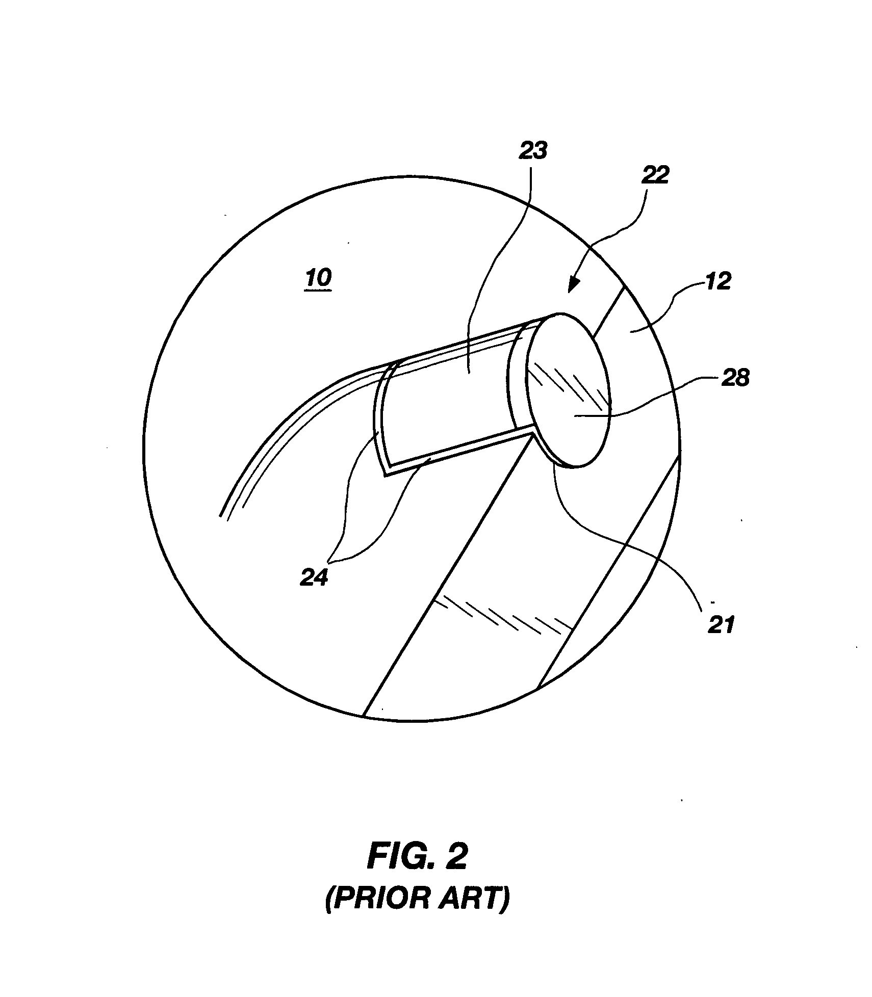
[0049] Embodiments of the invention may be used to enhance the wear resistance of rotary drill bits, particularly rotary drill bits having a particle-matrix composite material composition with an abrasive wear-resistant hardfacing material applied to surface portions thereof. A rotary drill bit 140 in accordance with an embodiment of the invention is shown in FIG. 5. The drill bit 140 includes a bit body 112 that has generally radially projecting and longitudinally extending wings or blades 114, which are separated by junk slots 116. As shown in FIG. 6, each of t...


PUM


Abstract

A rotary drill bit includes a bit body substantially formed of a particle-matrix composite material having an exterior surface and an abrasive wear-resistant material disposed on at least a portion of the exterior surface of the bit body. Methods for applying an abrasive wear-resistant material to a surface of a drill bit are also provided.

Description

PRIORITY CLAIM [0001] This application claims the benefit of U.S. Application Ser. No. 60 / 848,154, titled “EARTH-BORING ROTARY DRILL BITS INCLUDING WEAR-RESISTANT HARDFACING MATERIAL DISPOSED IN RECESSES FORMED IN EXTERIOR SURFACES THEREOF,” which was filed Sep. 29, 2006, and is a continuation-in-part of U.S. application Ser. No. 11 / 513,677, titled “COMPOSITE MATERIALS INCLUDING NICKEL-BASED MATRIX MATERIALS AND HARD PARTICLES, TOOLS INCLUDING SUCH MATERIALS, AND METHODS OF USING SUCH MATERIALS,” which was filed Aug. 30, 2006; U.S. application Ser. No. 11 / 272,439, titled “EARTH BORING ROTARY DRILL BITS AND METHODS OF MANUFACTURING EARTH BORING ROTARY DRILL BITS HAVING PARTICLE MATRIX COMPOSITE BIT BODIES,” which was filed Nov. 10, 2005; and U.S. application Ser. No. 11 / 223,215, titled “ABRASIVE WEAR-RESISTANT HARDFACING MATERIALS, DRILL BITS AND DRILLING TOOLS INCLUDING ABRASIVE WEAR-RESISTANT HARDFACING MATERIALS, METHODS FOR APPLYING ABRASIVE WEAR-RESISTANT HARDFACING MATERIALS TO...

Claims


Application Information

Patent Timeline
Patent Type & Authority Applications(United States)
IPC IPC(8): E21B10/46B24D3/10
CPCB22F2998/10C22C29/00C22C29/08E21B10/54B22F1/0003B22F3/15B22F3/10B22F1/09
Inventor STEVENS, JOHN H.OVERSTREET, JAMES LESLIEGILMORE, KENNETH E.MORGAN, JEREMY K.
Owner BAKER HUGHES INC
Why Eureka
Try Eureka