
Method and apparatus for attaching a membrane roof using an arm-held induction heating apparatus

a technology of induction heating apparatus and membrane roof, which is applied in the direction of electric heating, electric/magnetic/electromagnetic heating, roof tools, etc., to achieve the effects of greater heat transfer rate, greater tolerance in all directions for placement, and uniform thermal energy distribution

Inactive Publication Date: 2008-02-07
NEXICOR
View PDF11 Cites 25 Cited by
  • Summary
  • Abstract
  • Description
  • Claims
  • Application Information

AI Technical Summary

Benefits of technology

[0005]Accordingly, it is an advantage of the present invention to provide an induction heating tool used for membrane roofing in which the user can remain in a standing or walking position at all times while properly positioning the induction heating tool over one of the attachment disks.
[0006]It is another advantage of the present invention to provide an induction heating tool that is used to adhere an attachment disk to a membrane layer of a membrane roof structure, in which the induction heating tool provides a mechanical guide to readily allow the user to locate the attachment disks beneath the membrane layer.
[0007]It is yet another advantage of the present invention to provide an induction heating tool for use with a membrane roof in which the tool has an induction heating coil that is constructed in a triple racetrack coil configuration, and which allows for a greater tolerance in all directions for placement of the tool while heating an attachment disk that is positioned beneath the membrane layer.
[0008]It is a further advantage of the present invention to provide an induction heating tool for use with a membrane roof in which the tool has a heat spreader device positioned near the induction coil that assists in a more uniform thermal energy distribution, and which allows for a greater heat transfer rate away from the base of the tool that contains the induction coil.
[0009]It is still a further advantage of the present invention to provide an induction heating tool for use with a membrane roof in which the tool has the capability of being handled by a user's arm, in which some components are placed in a base or “bottom” portion on one end of a handle, while other components are placed on a “top” portion at the opposite end of the handle, thereby providing for a better weight distribution.
[0010]It is still another advantage of the present invention to provide an induction heating tool for use with a membrane roof in which the tool has a temperature sensor near the bottom of the base portion that contains the induction coil, and this temperature sensor can be used to “test” the effect of the magnetic field being generated by the induction coil to determine if the membrane layer of the roofing material has been sufficiently heated by use of the magnetic field.

Problems solved by technology

Moreover, this device is a rolling device, and is not a hand-held or arm-held device.

Method used


Image

  • Method and apparatus for attaching a membrane roof using an arm-held induction heating apparatus
  • Method and apparatus for attaching a membrane roof using an arm-held induction heating apparatus
  • Method and apparatus for attaching a membrane roof using an arm-held induction heating apparatus

Examples


Embodiment Construction

[0032]Reference will now be made in detail to the present preferred embodiment of the invention, an example of which is illustrated in the accompanying drawings, wherein like numerals indicate the same elements throughout the views.

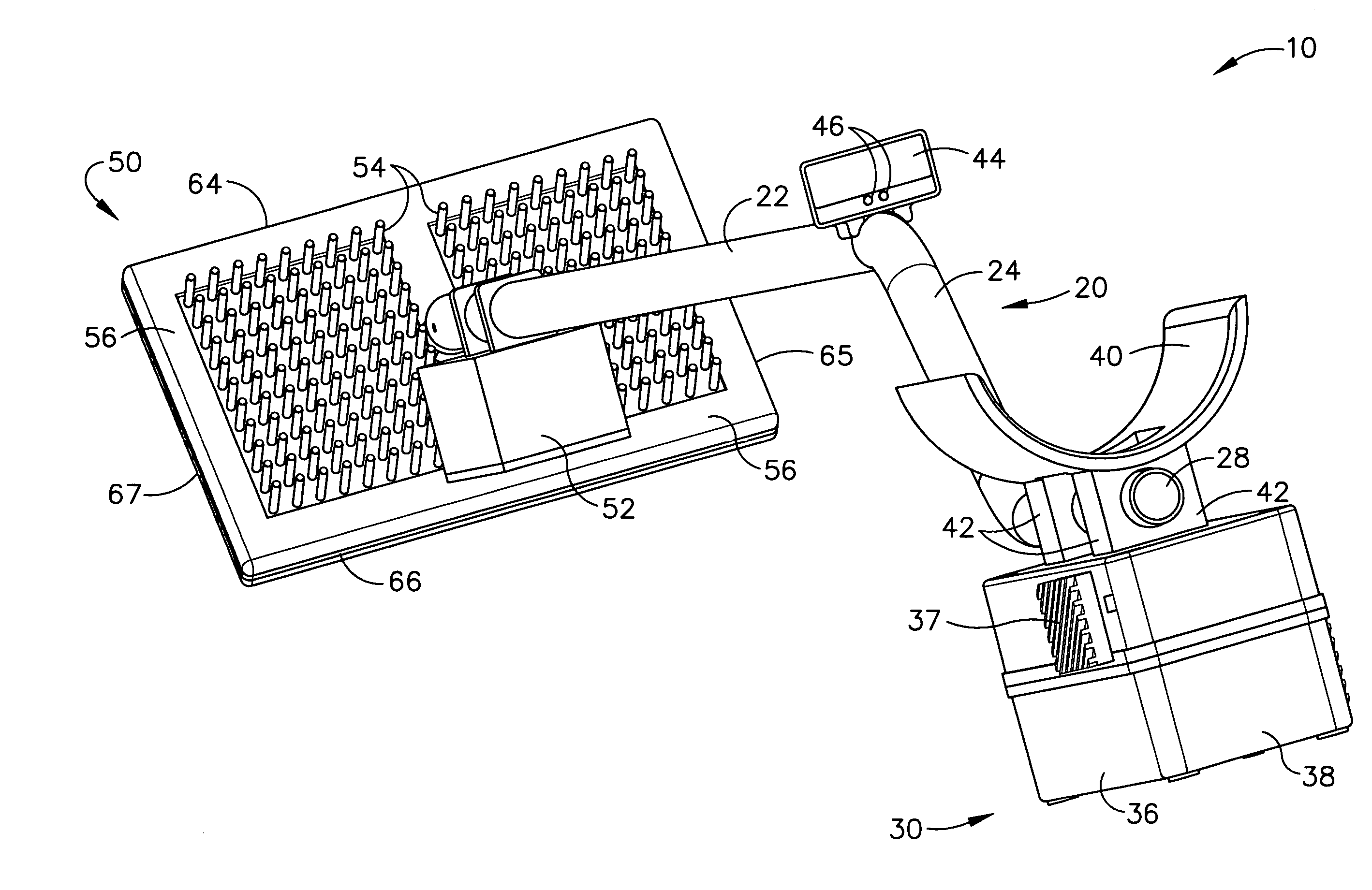
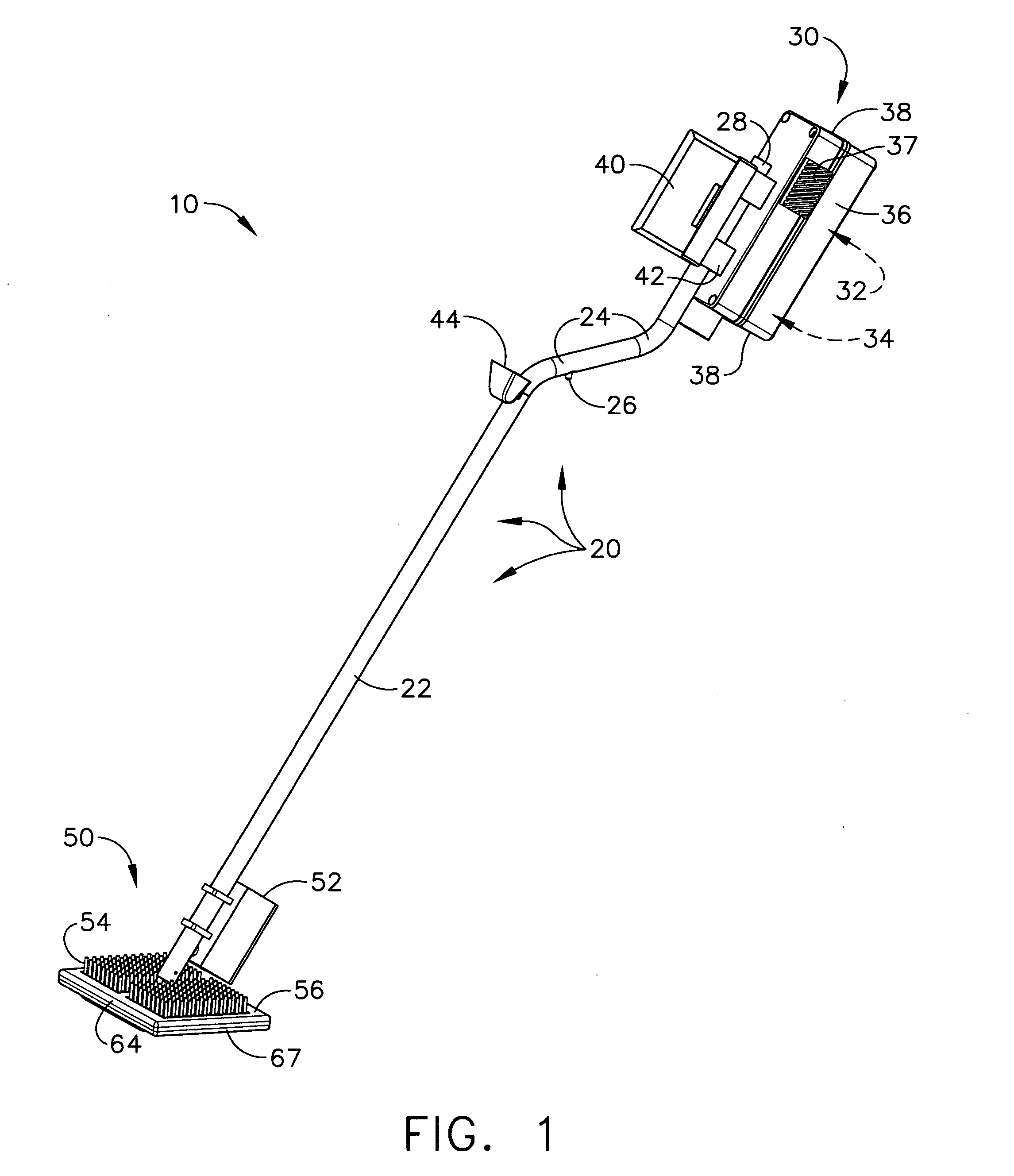
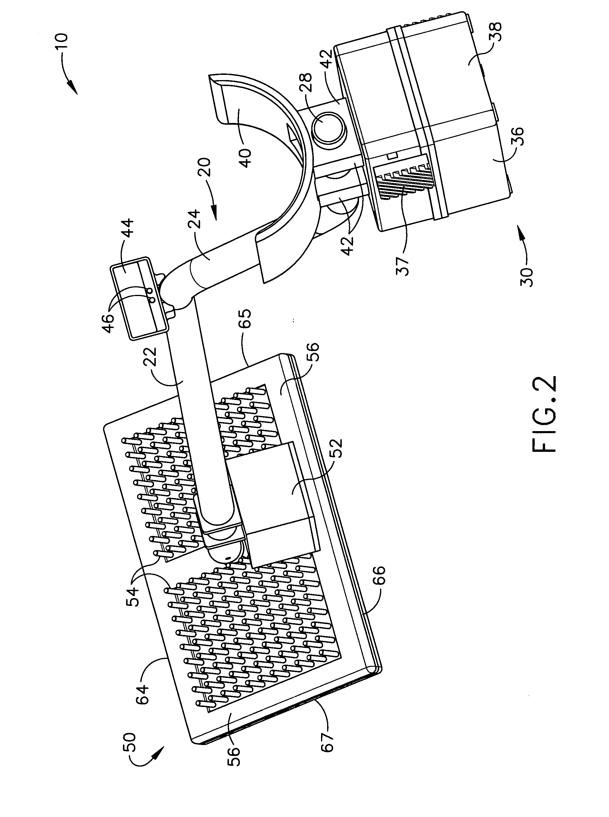
[0033]Referring now to FIG. 1, an induction heating tool generally designated by the reference numeral 10 is illustrated, having a handle portion 20, an electrical housing 30, and a base portion 50. Induction tool 10 is made to be portable, and is generally used in an upright position, in which the base portion 50 is the lowermost portion, and the handle portion 20 connects the base portion 50 to the electrical housing 30 neat the top of the unit. The electrical housing 30 contains several electrical components, typically including a controller and power supply 32, and a coil driver circuit 34. In general, the type of controller and power supply that would be suitable for the induction tool 10 are described in U.S. Pat. No. 6,509,555.

[0034]Handle portion ...


PUM


Abstract

An improved induction heating apparatus is provided for attaching membrane roofs. A top membrane layer is attached to attachment disks that hold sheets of thermal insulation to the top of roof substrates. The heating apparatus emits a magnetic field that raises the temperature of the disks and a heat-activated adhesive on top of the disks which, after cooling, becomes adhered to the bottom surface of the top membrane layer. The disks in turn are attached via fasteners to the substrate portion of the roof structure. The apparatus includes a set of bottom guides that allow a user to find the attachment disks mechanically, without actually seeing those disks beneath the top membrane layer. A triple-racetrack coil provides improved positioning tolerance in all directions, for coil placement during a heating event. An optional temperature sensor can “test” the heating effect on the top membrane layer, during / after a heating event.

Description

CROSS-REFERENCE TO RELATED APPLICATIONS[0001]The present application claims priority to provisional patent application Ser. No. 60 / 832,728, titled “METHOD AND APPARATUS FOR ATTACHING A MEMBRANE ROOF USING AN ARM-HELD INDUCTION HEATING APPARATUS,” filed on Jul. 21, 2006.TECHNICAL FIELD[0002]The present invention relates generally to induction heating equipment and is particularly directed to an induction heating apparatus of the type which attaches membrane roofs. The invention is specifically disclosed as a method and apparatus used to attach a top membrane layer to attachment disks that hold sheets of thermal insulation to the top of roof structures. The apparatus includes a self-contained power supply and a controller that provides alternating current of an appropriate frequency to an induction “work” coil that emits a magnetic field, which is used to induce eddy currents in the metal attachment disks, thereby raising the temperature of those disks. The upper surface of the disks ...

Claims


Application Information

Patent Timeline
IPC IPC(8): H05B6/10
CPCE04D15/04H05B6/105
Inventor BARBER, JOHN P.CHALLITA, ANTONIOS
Owner NEXICOR
Learn More