Thyristor controlled alternating current demagnetizer

Inactive Publication Date: 2008-02-07
ELECTRO MATIC PRODS
View PDF4 Cites 7 Cited by
  • Summary
  • Abstract
  • Description
  • Claims
  • Application Information

AI Technical Summary

Benefits of technology

[0014]A microcontroller based power control sends bursts of energy in succession to demagnetizing coil(s

Problems solved by technology

The disadvantage of this method is that coil(s) have to be designed to run continuously to dissipate supplied power.
Another disadvantage of previous technology is that object(s) can become accidentally re-magnetized if the object(s) are either incorrectly passed over the demagnetizing surface, or if power is removed from the coil(s) while object is in the magnetic field range.

Method used


Image

  • Thyristor controlled alternating current demagnetizer
  • Thyristor controlled alternating current demagnetizer
  • Thyristor controlled alternating current demagnetizer

Examples


Embodiment Construction

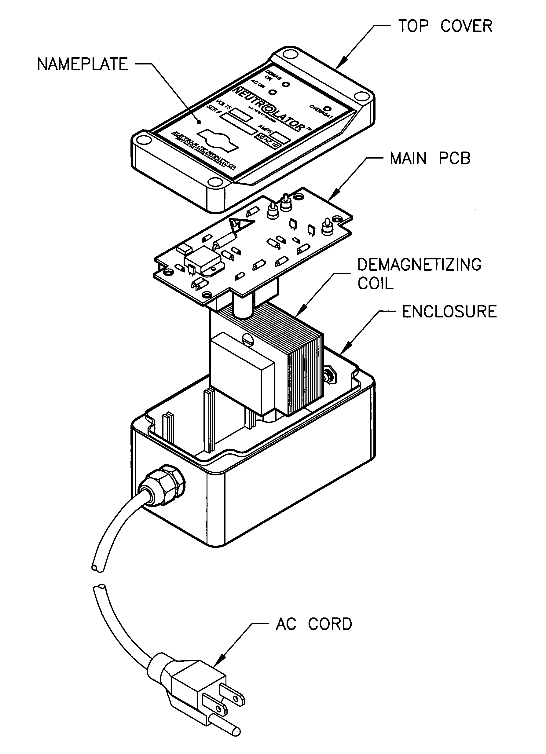
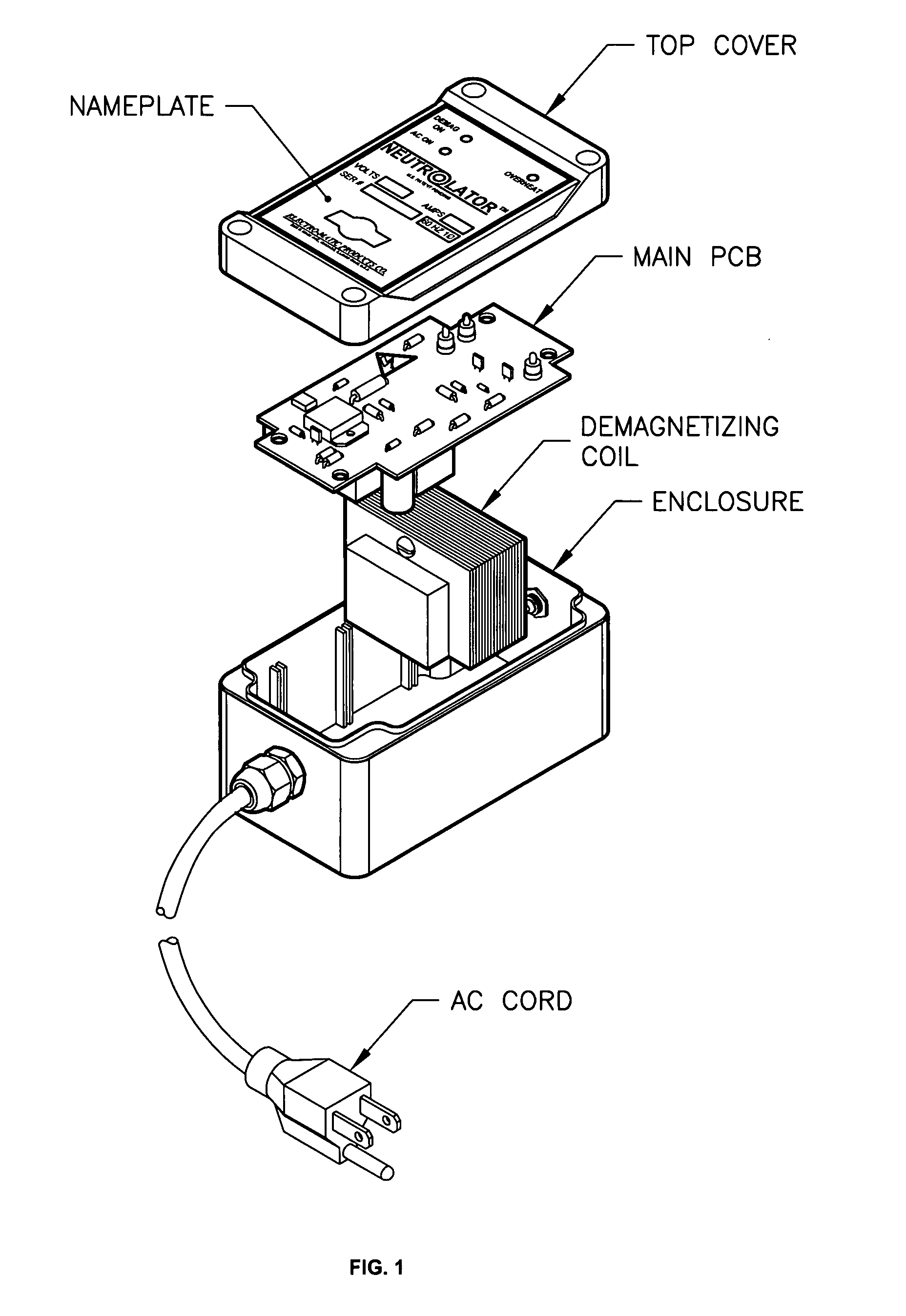
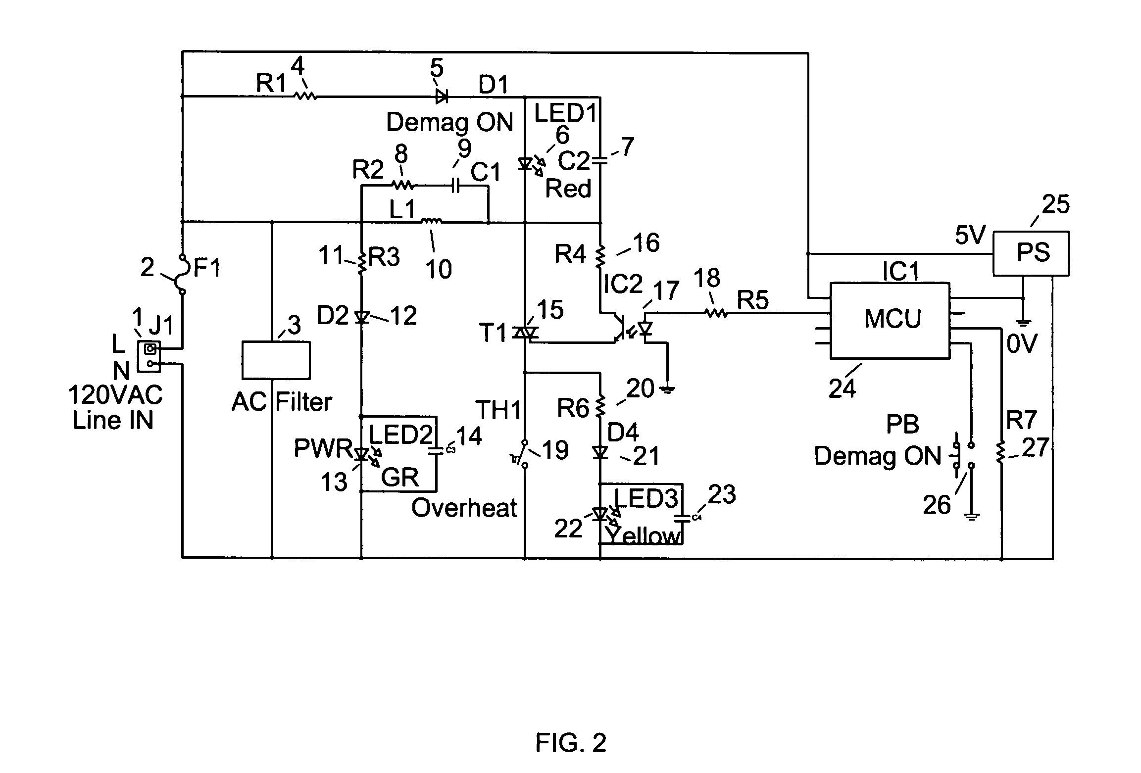
[0017]The system is comprised of demagnetizing coil(s) and a microcontroller based power control. The power control sends bursts of energy in succession to demagnetizing coil(s) thereby demagnetizing ferromagnetic materials by exposing them to alternating decaying magnetic fields.

[0018]Included in the microcontroller based power control are visual indicators to show present status of input power, coil energy, and temperature condition. Also included in the control are resistor(s), rectifier(s) diode(s), filter capacitor(s), optocoupler(s), fuse(s), filter(s), power supply(s) and triac(s).

Operation of System:

[0019]Input power is fed through input line power connector at 1 protected by the fuse at 2 and filtered by AC filter at 3.

[0020]The demagnetizer has 3 different visual indicators for present input AC power indicated by green LED at 13. The power supply for this diode consists of resistor at 11, rectifier diode at 12 and filter capacitor at 14. The red LED at 6 is indicating tha...


PUM


Abstract

This unit is intermittent duty, small, and light weight. Use of a thyristor(s) control reduces the unit's energy consumption through reduced AC input voltage while still producing sufficient demagnetizing power and effective demagnetizing results.This principle may be applied to ANY and ALL sizes of demagnetizing coils.With the burst control we can achieve same demagnetizing power and reduce overall power consumption of the demagnetizing coil(s) reducing size and weight of the coil(s). For this intermittent duty coil(s) the power consumption is reduced by over 40% and heating rate reduced which allows approx. 40% longer continuous running time.

Description

CROSS REFERENCE TO RELATED APPLICATIONS[0001]This application claims the benefit of PPA Ser. No. 60 / 883,389, filed Jul. 27, 2006 by the present inventor(s).FEDERALLY SPONSORED RESEARCH [0002]Not applicableSEQUENCE LISTING OF PROGRAM[0003]Not applicableBACKGROUND OF INVENTION[0004]1. Field of Invention[0005]This invention relates to a microcontroller based power control, specifically to control power supplied to demagnetizing coil(s).[0006]2. Prior Art[0007]3. Objects and Advantages[0008]Ferromagnetic objects are demagnetized by exposing the object(s) to alternating decaying magnetic fields.[0009]Previously, exposure to alternating magnetic fields was accomplished by uncontrolled utility sine wave power to multi-turn coil(s) inserted in a stack of E-core laminations. The object would have to be manually passed over demagnetizing coil(s) and then moved away from the coil(s), thereby creating an alternating decaying magnetic field. The disadvantage of this method is that coil(s) have t...

Claims


Application Information

Patent Timeline
IPC IPC(8): H01F13/00
CPCH01F13/006
Inventor KAHRIMANOVIC, ELVIRLITTWIN, KENNETH M.
Owner ELECTRO MATIC PRODS
Why Eureka
Try Eureka