Planar Lightwave Circuit Based Wavelength Selective Switch

a technology of lightwave circuit and wavelength selective switch, which is applied in the direction of multiplex communication, instruments, optical elements, etc., can solve the problems of not being able to achieve the effect of integrating the mems array on the plc, and the external lens having to be extremely well aligned

Active Publication Date: 2008-02-07
LUMENTUM OPERATIONS LLC
View PDF13 Cites 13 Cited by
  • Summary
  • Abstract
  • Description
  • Claims
  • Application Information

AI Technical Summary

Problems solved by technology

However, there is as yet no practical way of including the MEMS array on the PLC.
Consequently, not only is the external lens required to be extremely well aligned, i.e. relatively expensive and extremely sensitive to misalignments, but the optical path is necessarily mostly in air.

Method used


Image

  • Planar Lightwave Circuit Based Wavelength Selective Switch
  • Planar Lightwave Circuit Based Wavelength Selective Switch
  • Planar Lightwave Circuit Based Wavelength Selective Switch

Examples


Embodiment Construction

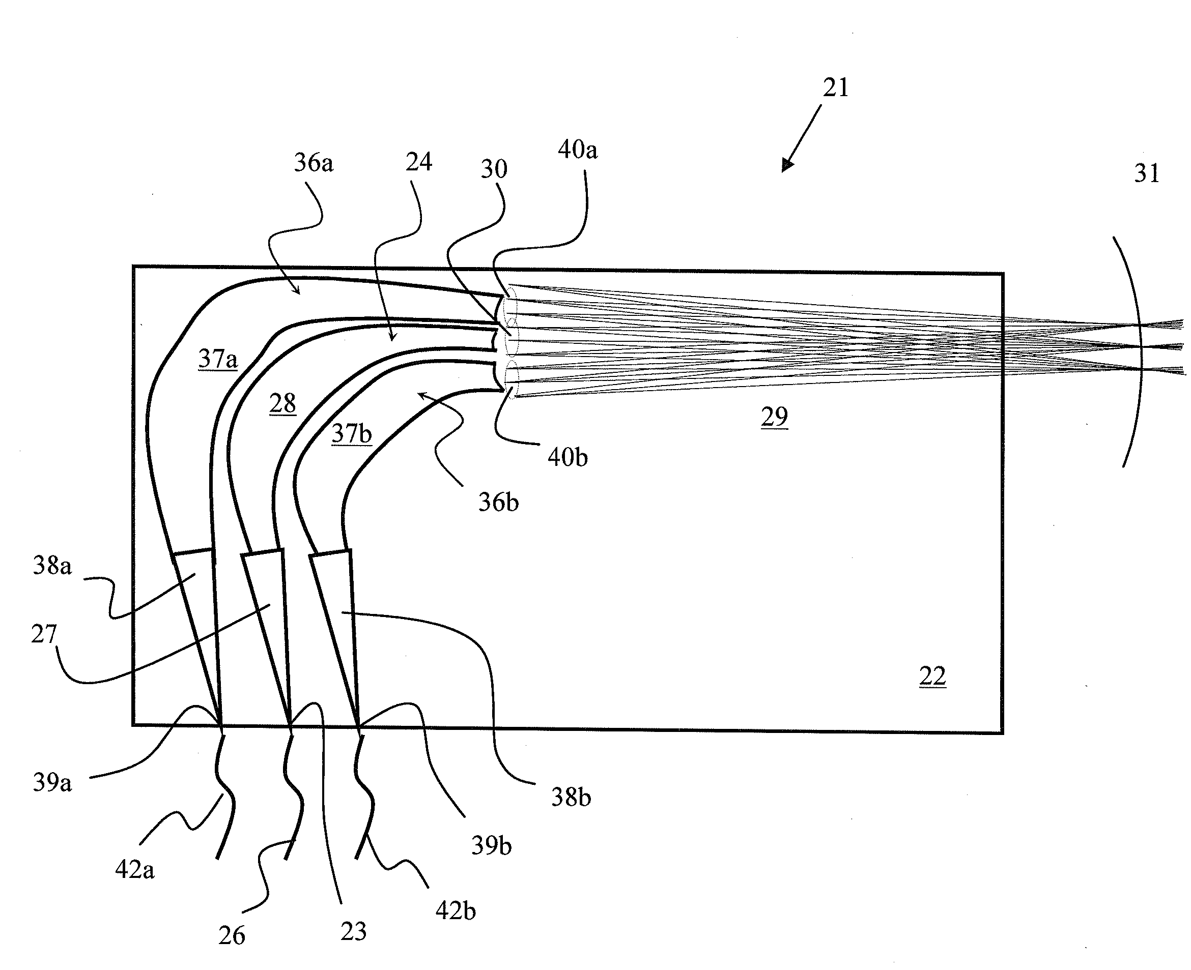
[0035]The present invention extends the concept of a standard array waveguide grating (AWG), which focuses each wavelength component to a Rowland circle inside the chip where discrete waveguides are located, to one which focuses each wavelength component outside of the chip, and then place a MEMS mirror array at the focus location. With reference to FIG. 3, a basic device 21 according to the present invention includes a PLC chip 22 with an input port 23 at an edge thereof enabling a first AWG 24 to be optically coupled to an input fiber 26. An input optical signal, including one or more wavelength channels, is launched from the input fiber 26 into the AWG 24 via the input port 23, and diffracts, in one dimension, within entrance slab waveguide section 27 to an array of channel waveguides 28. The outputs of the channel waveguides 28 interface with a long output slab waveguide region 29 along an interface, which is curved forming a virtual sub-pupil 30 with optical power, whereby the ...


PUM


Abstract

The present invention extends the concept of a standard array waveguide grating (AWG), which focuses each wavelength component launched via an input AWG to a Rowland circle inside a planar lightwave chip (PLC) where discrete waveguides are located, to one which focuses each wavelength component outside of the PLC chip along a straight line. An array of MEMS mirrors or other redirecting elements is positioned at the focus location for independently redirecting each of the wavelength channels back to any number of selected output AWGs formed on the same PLC chip as the input AWG.

Description

CROSS-REFERENCE TO RELATED APPLICATIONS[0001]The present invention claims priority from U.S. Patent Application No. 60 / 821,346 filed Aug. 3, 2006, which is incorporated herein by reference.TECHNICAL FIELD[0002]The present invention relates to a wavelength selective switch (WSS), and in particular to a WSS based on planar lightwave circuit (PLC) technology.BACKGROUND OF THE INVENTION[0003]Conventional optical wavelength dispersive devices, such as those disclosed in U.S. Pat. No. 6,097,859 issued Aug. 1, 2000 to Solgaard et al; U.S. Pat. No. 6,498,872 issued Dec. 24, 2002 to Bouevitch et al; U.S. Pat. No. 6,707,959 issued Mar. 16, 2004 to Ducellier et al; U.S. Pat. No. 6,810,169 issued Oct. 26, 2004 to Bouevitch; U.S. Pat. No. 6,922,239 issued to Solgaard et al; and U.S. Pat. No. 7,014,326 issued Mar. 21, 2006 to Danagher et al, separate a multiplexed optical beam into constituent wavelengths, and then direct individual wavelengths or groups of wavelengths, which may or may not have ...

Claims


Application Information

Patent Timeline
Patent Type & Authority Applications(United States)
IPC IPC(8): G02B6/35
CPCG02B6/12011G02B6/12019G02B6/356G02B6/3522G02B6/3512
Inventor FONDEUR, BARTHELEMYCRAFTS, DOUGLAS E.RANALLI, ELISEO
Owner LUMENTUM OPERATIONS LLC
Why Eureka
Try Eureka