Bearing Support Structure and a Gas Turbine Engine Comprising the Bearing Support Structure

a technology of bearing support and gas turbine engine, which is applied in the direction of machines/engines, liquid fuel engines, mechanical equipment, etc., can solve the problems of cumbersome installation of the structure in the engine and removal of the engine, time-consuming process for producing such a bearing house and mounting it in the engine, and the position of the two bearings, etc., to achieve convenient modification of the bearing support structure, easy installation and removal from the engine, and sufficient stiffness

Inactive Publication Date: 2008-02-07
VOLVO AERO CORP
View PDF6 Cites 51 Cited by
  • Summary
  • Abstract
  • Description
  • Claims
  • Application Information

AI Technical Summary

Benefits of technology

[0017] One problem with prior known solutions is that the positions of the two bearings are set from rotordynamical requirements. One of the bearings (or both bearings) may then end up in a position far from the most favourable position with regard to loads and torsional moments; vertically below the engine mount. One advantage with the inventive solution is that the design of the bearing support structure may be amended easily by replacing one of the conical plate-shaped parts with another part having a different inclination and / or length and / or material.
[0018] It is also desirable to achieve a gas turbine engine with a bearing support structure “between radially inner first and second bearings adapted to rotatably support a first and a second rotor, respectively, and a radially outer engine frame, which structure has a sufficient stiffness for transferring bearing loads and is easy to install and remove from the engine. The bearing support structure is preferably arranged between the high pressure turbine and the low pressure turbine in the direction of the engine longitudinal central axis.

Problems solved by technology

The process for producing such a bearing house and to mount it in the engine is time-consuming.
The position of the bearings and the construction of the bearing support structure makes installation of the structure in the engine and removal of it from the engine cumbersome.
One problem with prior known solutions is that the positions of the two bearings are set from rotordynamical requirements.

Method used


Image

  • Bearing Support Structure and a Gas Turbine Engine Comprising the Bearing Support Structure
  • Bearing Support Structure and a Gas Turbine Engine Comprising the Bearing Support Structure
  • Bearing Support Structure and a Gas Turbine Engine Comprising the Bearing Support Structure

Examples


Embodiment Construction

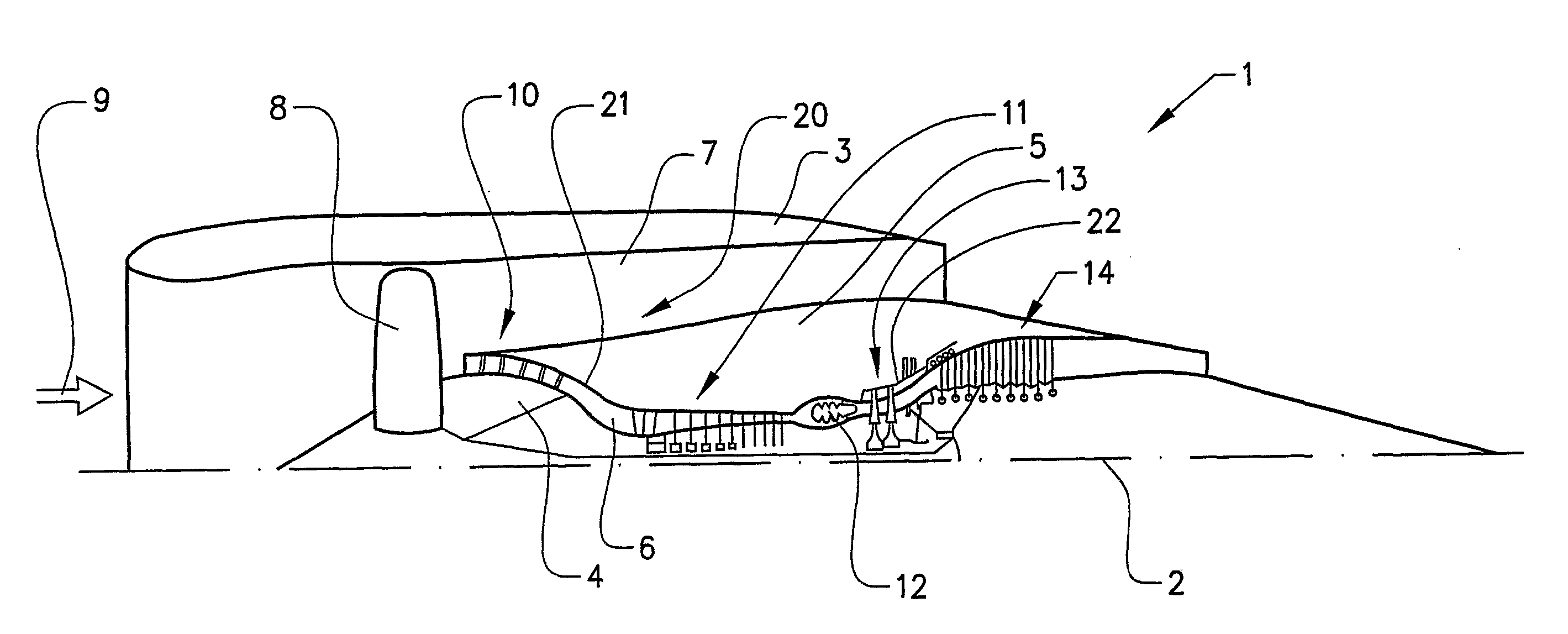
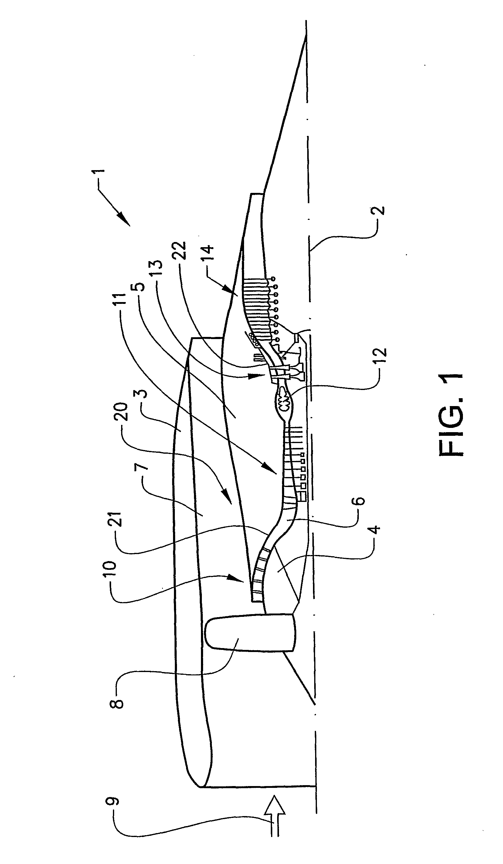
[0024] The invention will below be described for a turbofan gas turbine aircraft engine 1, which in FIG. 1 is circumscribed about an engine longitudinal central axis 2. The engine 1 comprises an outer casing or nacelle 3, an inner casing 4 (rotor) and an intermediate casing 5 which is concentric to the first two casings and divides the gap between them into an inner primary gas channel 6 for the compression of air and a secondary channel 7 in which the engine bypass air flows. Thus, each of the gas channels 6,7 is annular in a cross section perpendicular to the engine longitudinal central axis 2.

[0025] The engine 1 comprises a fan 8 which receives ambient air 9, a booster or low pressure compressor (LPC) 10 and a high pressure compressor (HPC) 11 arranged in the primary gas channel 6, a combustor 12 which mixes fuel with the air pressurized by the high pressure compressor 11 for generating combustion gases which flow downstream through a high pressure turbine (HPT) 13 and a low pre...


PUM


Abstract

A bearing support structure is provided for installation in a gas turbine engine between radially inner first and second bearings adapted to rotatably support a first and a second rotor, respectively, and a radially outer engine frame. The support structure includes a first annular plate-shaped part and an arrangement for supporting the first bearing at one end thereof and a second annular plate-shaped part and an arrangement for supporting the second bearing at one end thereof. The first and second plate-shaped parts are joined together forming a one-piece unit for installation in the gas turbine engine.

Description

BACKGROUND AND SUMMARY [0001] The present invention relates to a bearing support structure for installation in a gas turbine engine between radially inner first and second bearings adapted to rotatably support a first and a second rotor, respectively, and a radially outer engine frame, the support structure comprising a first annular plate-shaped part and means for supporting the first bearing at one end thereof and a second annular plate-shaped part and means for supporting the second bearing at one end thereof. The invention also relates to a gas turbine engine comprising the bearing support structure. [0002] The bearing support structure may be used in stationary gas turbine engines, but is especially advantageous for aircraft jet engines. Jet engine is meant to include various types of engines, which admit air at relatively low velocity, heat it by combustion and shoot it out at a much higher velocity. Accommodated within the term jet engine are, for example, turbojet engines an...

Claims


Application Information

Patent Timeline
Patent Type & Authority Applications(United States)
IPC IPC(8): F01D25/16F02C
CPCY02T50/671F01D25/162Y02T50/60
Inventor SJOQVIST, ROGER
Owner VOLVO AERO CORP
Why Eureka
Try Eureka