Drill stack formation

a technology of stack formation and drill bit, which is applied in the direction of tool workpiece connection, manufacturing tools, transportation and packaging, etc., can solve the problems of the whole stack of sheets expanding and the excessive thickness of the overall stack, and achieve the effect of preventing burr formation

Inactive Publication Date: 2008-02-07
GLOBALFOUNDRIES INC
View PDF3 Cites 3 Cited by
  • Summary
  • Abstract
  • Description
  • Claims
  • Application Information

AI Technical Summary

Benefits of technology

[0010] a plurality of stacks wherein each successive stack is coupled with a removable adhesive to a

Problems solved by technology

This results in the whole stack of sheets expanding.
The thickness of the epoxy between each sheet results in excessive thickne

Method used


Image

  • Drill stack formation
  • Drill stack formation
  • Drill stack formation

Examples


first embodiment

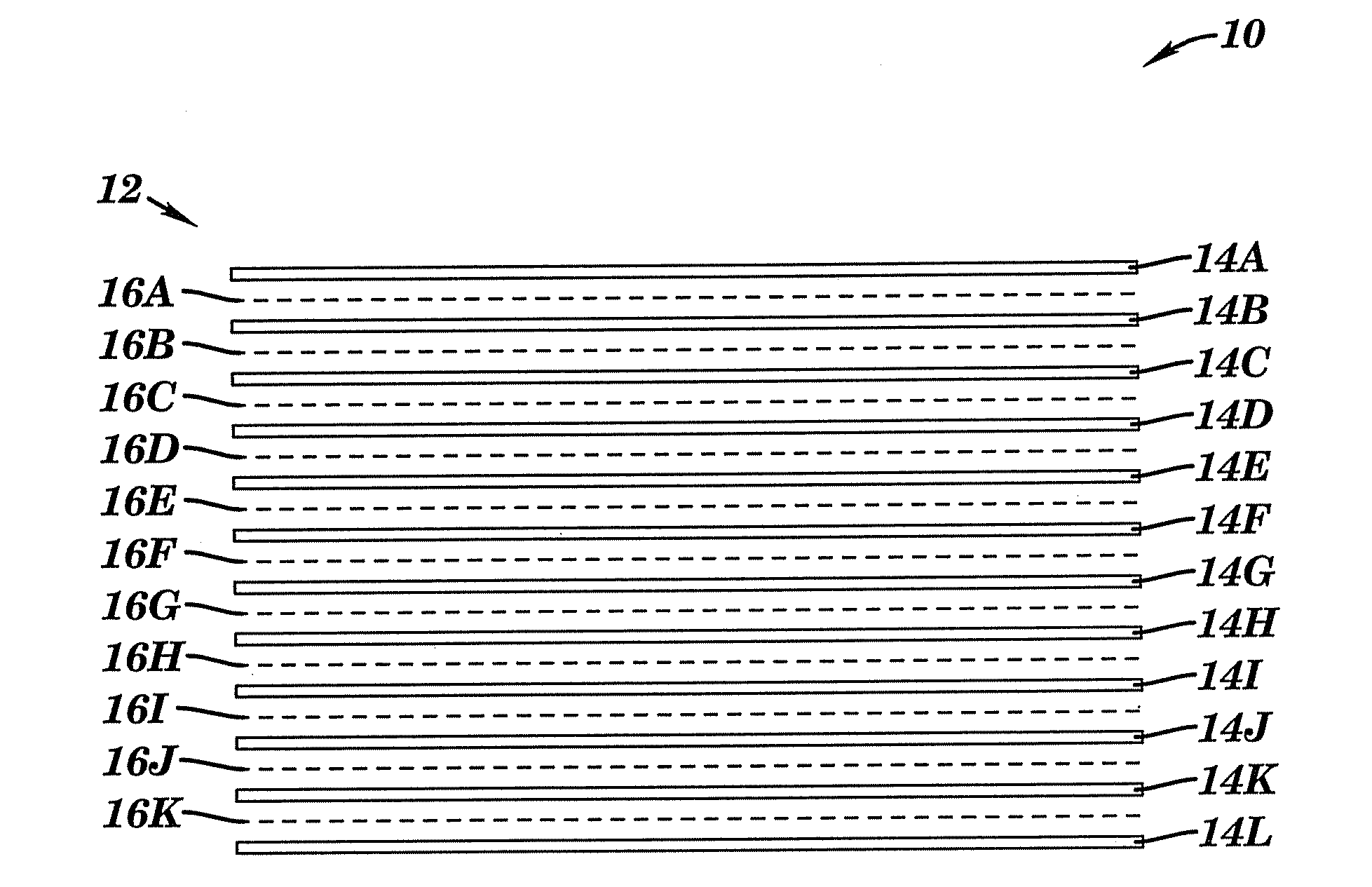
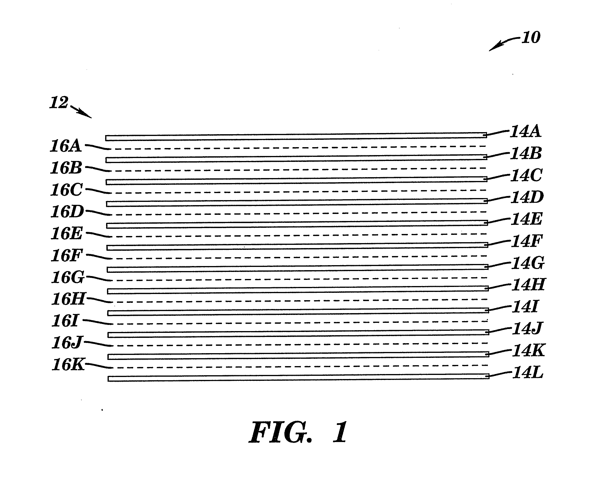
[0034]FIG. 1 illustrates a schematic view of a laminated structure 10 including a stack 12 in accordance with a The stack 12 includes a plurality of sheets 14A-14L. A removable adhesive 16A-16K is applied between each sheet 14A-14L, respectively. The sheets 14A-14L may comprise any suitable material (e.g., copper, invar, copper-invar-copper, etc.). Invar is an iron-nickel alloy. The removable adhesive 16A-16K may comprise any suitable material (e.g., fructose, sucrose, water soluble polymers, water, etc.). The material may comprise any suitable form (e.g., powered fructose, a liquid, a liquid solution, etc.).

second embodiment

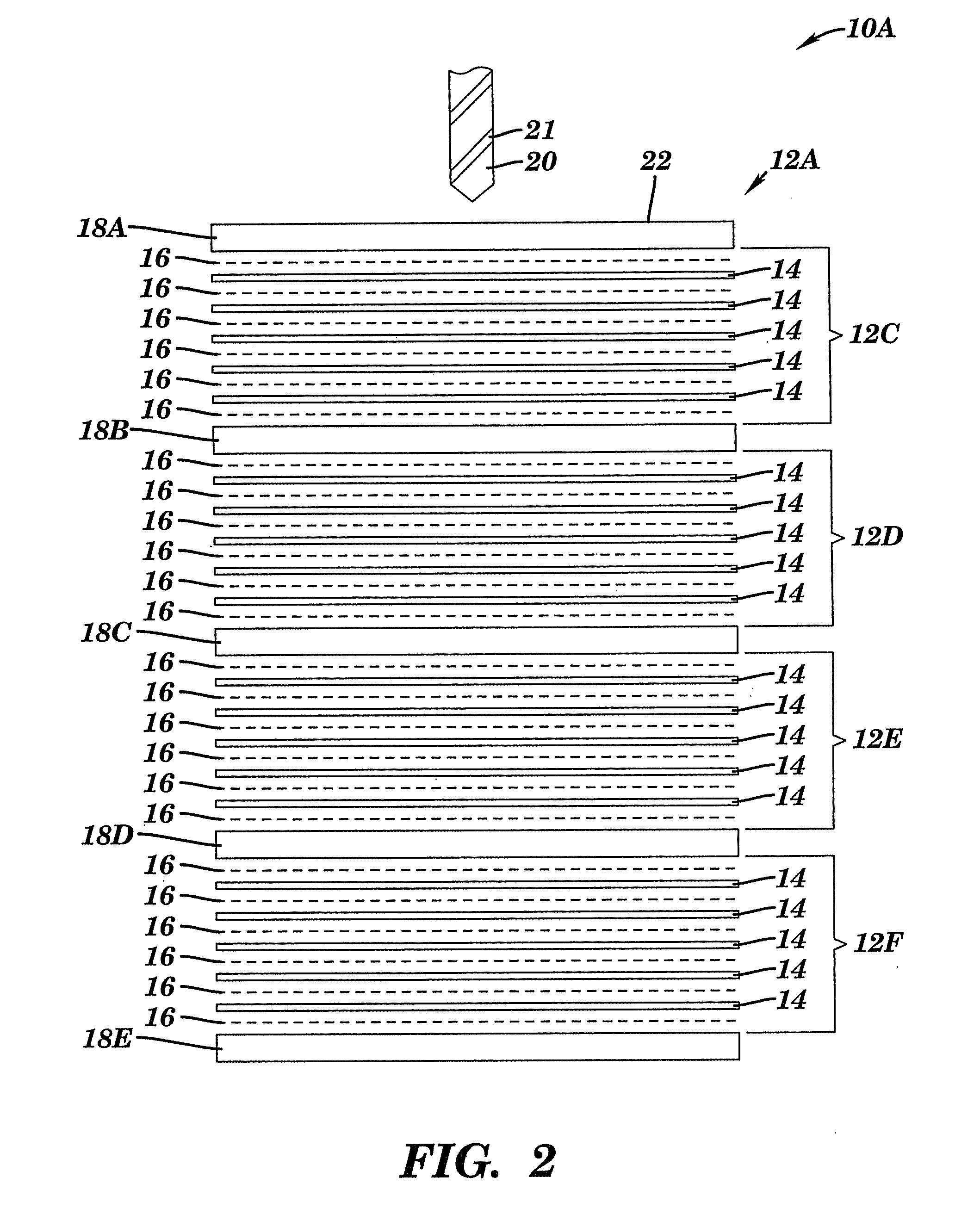
[0035]FIG. 2 illustrates a laminated structure 10A including a stack 12A in accordance with a The stack 12A includes a plurality of stacks 12C, 12D, 12E, and 12F interspersed with a plurality of layers 18A-18E. Each stack 12C, 12D, 12E and 12F includes a plurality of sheets 14 with removable adhesive placed between each sheet 14. Also, the removable adhesive 16 is placed between each layer 18A-18E and each adjacent sheet 14. Each layer 18B and 18C prevents chip build up within drill bit flutes 21 by providing an interruption in the sheet 14 being drilled. Each layer 18A-18E comprises any suitable soft material (e.g., impregnated and laminated epoxy / glass, phenolic / paper laminate, aluminum, etc.). The formation chips are broken off each time the drill bit 20 passes from one material to a dissimilar material. For example, if each sheet 14 is copper, and each layer 18A-18E is (aluminum or paper / phenolic), then any tendency for chip build up would be interrupted each time the drill bit...

third embodiment

[0036]FIG. 3 illustrates a laminated structure 10B including a stack 12B in accordance with a The stack 12B includes a plurality of sheets 14. The removable adhesive 16 is applied between each sheet 14. The stack 12B includes a first surface 24 and a second surface 26. A first surface 28A of a first layer 18F is coupled with the removable adhesive 16 to the first surface 24 of the stack 12B. A first surface 30A of a second layer 18G is coupled with the removable adhesive 16 to the second surface 26 of the stack 12B. A first surface 32A of a first foil 34A contacts a second surface 28B of the first layer 18F. A first surface 36A of a second foil 34B contacts a second surface 30B of the second layer 18G.

[0037] A first surface 38A of a first plate 50A contacts a second surface 32B of the first foil 34A. A first surface 40A of a second plate 50B contacts a second surface 36B of the second foil 34B. A first surface 42A of a third plate 50C contacts a second surface 38B of the first plat...


PUM

PropertyMeasurementUnit
Temperatureaaaaaaaaaa

Abstract

A structure. The structure includes a stack of two or more sheets. Successive sheets in each pair of successive sheets of the stack are adhesively coupled to each other by an adhesive layer consisting of a removable adhesive that is removable if heated to an elevated temperature at which the removable adhesive melts. The removable adhesive is also disposed on top and bottom surfaces of the stack. The removable adhesive consists of a liquid while adhesively coupling the successive sheets to each other. A first surface of a first layer coupled with the removable adhesive to a first surface of the stack. A first surface of a second layer is coupled with the removable adhesive to a second surface of the stack. The first and second layers are adapted to prevent burr formation in a hole subsequently drilled through the stack.

Description

[0001] This application is a continuation application claiming priority to Ser. No. 10 / 691,882, filed Oct. 23, 2003; which is a divisional of U.S. Pat. No. 6,669,805, issued Dec. 30, 2003.BACKGROUND OF THE INVENTION [0002] 1. Technical Field [0003] The present invention relates to a method of temporarily adhering a stack of sheets together to facilitate drilling a hole through the stack of sheets. [0004] 2. Related Art [0005] A stack of sheets may be adhered together around a periphery of each sheet using an adhesive such as a glass cloth impregnated with epoxy. Hole burring occurs as a drill passes through the stack. Additionally, each sheet separates from an adjacent sheet as the drill passes between the sheets. This results in the whole stack of sheets expanding. An alternate method includes the permanent application of cured epoxy over the entire surface of each sheet in the stack. The thickness of the epoxy between each sheet results in excessive thickness of the overall stack ...

Claims


Application Information

Patent Timeline
IPC IPC(8): B32B15/08B32B7/12B32B15/01B32B15/04B32B15/20H05K3/00H05K3/44
CPCB23B35/00Y10T408/03B23B2222/41B23B2222/64B23B2240/21B32B7/06B32B7/12B32B15/01B32B15/04B32B15/20H05K3/0047H05K3/44H05K2203/1536Y10T156/1184Y10T428/2804Y10T428/28Y10T428/14Y10T428/1495Y10T428/12569Y10T156/1057Y10T428/24322Y10T428/24273B23B2222/21Y10T83/0476
Inventor JAPP, ROBERT M.KEVERN, GREGORY A.POCH, FRANCIS S.
Owner GLOBALFOUNDRIES INC
Why Eureka
Try Eureka