External Defibrillator

a technology of external defibrillators and external electrodes, which is applied in the field of external defibrillators, can solve the problems of wearable defibrillators, lack of patient compliance, and lifevest products, and achieve the effects of avoiding permanent devices, minimal maintenance or care, and automatic operation

Active Publication Date: 2008-02-07
ELEMENT SCI
View PDF16 Cites 215 Cited by
  • Summary
  • Abstract
  • Description
  • Claims
  • Application Information

AI Technical Summary

Benefits of technology

[0008]One drawback of currently available wearable defibrillators (such as the LifeVest product) is lack of patient compliance. Because of the size, shape and weight of these wearable devices, patients are reluctant to wear them due to discomfort, their bulkiness under clothes or limitations in the devices themselves. In particular, such devices cannot be worn in the shower or bath, and they often are difficult, if not impossible, to sleep in. What is needed, therefore, is a non-invasive, temporary device that can monitor the patient's heart rhythm to detect arrhythmias; can automatically and reliably defibrillate the heart if an arrhythmia is detected; can be used for a short period of time (days to weeks, possibly months) when the temporary risk of an arrhythmia exists; is entirely non-invasive and reversible and causes no significant or potentially permanent bodily harm from its use; and / or, most importantly, is unobtrusive and waterproof and requires only minimal maintenance or care so that it can seamlessly integrate into patients' lives such that they are protected from life-threatening arrhythmias during this entire period of time. If the device is required to defibrillate a patient during this time, this patient can then be referred for implantation of a permanent ICD, if appropriate. If nothing occurs and the patient doesn't have persistent pro-arrhythmic risk factors after this temporary period, the device can be removed and the implantation of a permanent device can be avoided. In this way, a functional, easy-to-use device for cardiac defibrillation to protect patients during a period of temporarily increased arrhythmia risk could also more efficiently identify patients who would benefit from more permanently implanted devices and those who would not.

Problems solved by technology

One drawback of currently available wearable defibrillators (such as the LifeVest product) is lack of patient compliance.
Because of the size, shape and weight of these wearable devices, patients are reluctant to wear them due to discomfort, their bulkiness under clothes or limitations in the devices themselves.
In particular, such devices cannot be worn in the shower or bath, and they often are difficult, if not impossible, to sleep in.

Method used


Image

  • External Defibrillator
  • External Defibrillator
  • External Defibrillator

Examples


Embodiment Construction

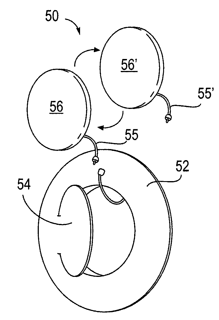
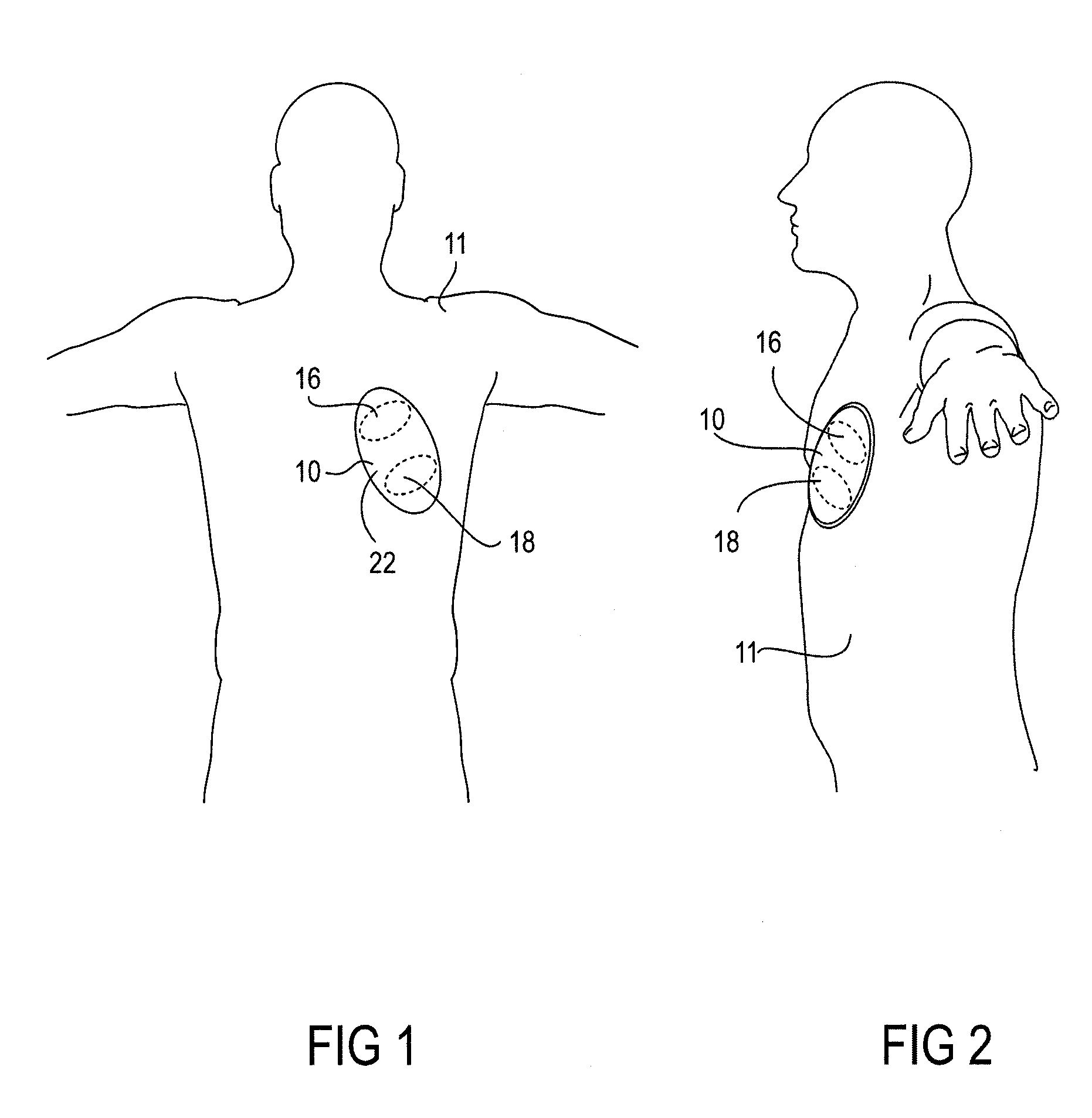
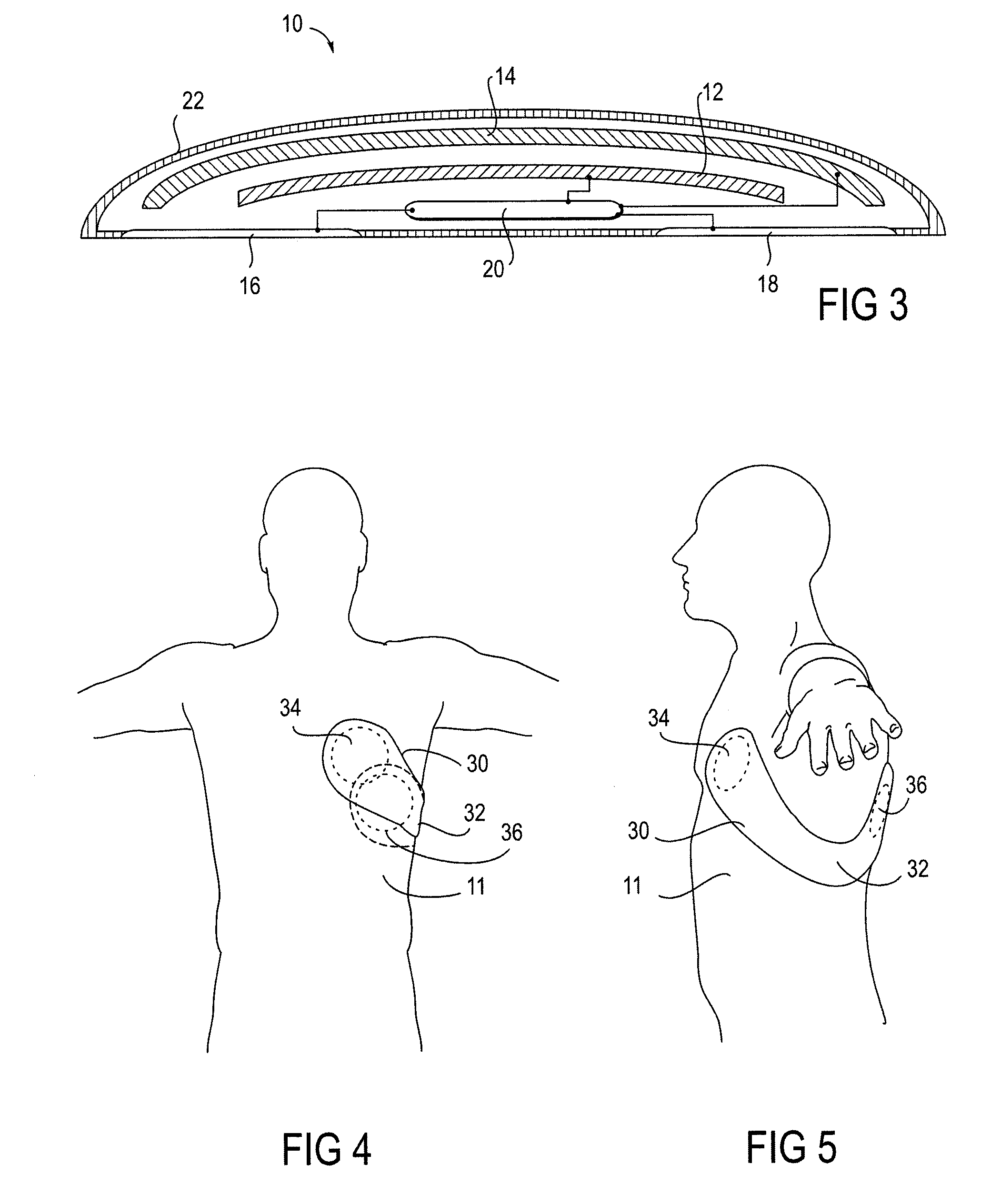
[0031]FIGS. 1-3 show one embodiment of the external defibrillator of this invention. (For purposes of this application, the terms “defibrillator” and “external defibrillator” include external cardioverters and cardioverter defibrillators as well.) As shown in FIGS. 1 and 2, defibrillator 10 has been engaged with a patient 11 by attaching to the front of the patient's torso. In this embodiment, defibrillator 10 has a battery 12, a capacitor 14, a pair of electrodes 16 and 18, and a controller 20. Capacitor 14 may have a capacitance between 25 and 300 micro Farads. Electrodes 16 and 18 are preferably at least 3 inches apart in order to place them in the proper orientation for use on an adult. In some embodiments, more than two electrodes may be used. A support 22 supports the battery, capacitor, electrodes and controller. In this embodiment, support 24 is a waterproof housing. Adhesive 24 on the electrode side of the defibrillator may be used to attach the defibrillator to the patient...


PUM


Abstract

An external defibrillator having a battery; a capacitor electrically communicable with the battery; at least two electrodes electrically communicable with the capacitor and with the skin of a patient; a controller configured to charge the capacitor from the battery and to discharge the capacitor through the electrodes; and a support supporting the battery, capacitor, electrodes and controller in a deployment configuration, the defibrillator having a maximum weight per unit area in the deployment configuration of 0.1 lb/in2 and/or a maximum thickness of 1 inch. The support may be a waterproof housing.

Description

CROSS REFERENCE TO RELATED APPLICATIONS[0001]This application claims priority under 35 U.S.C. § 119 to U.S. Provisional Patent Application No. 60 / 834,556, filed Aug. 1, 2006, and entitled “Non-Invasively Affixed Device for Cardiac Defibrillation,” which is incorporated by reference in its entirety.INCORPORATION BY REFERENCE[0002]All publications and patent applications mentioned in this specification are herein incorporated by reference to the same extent as if each individual publication or patent application was specifically and individually indicated to be incorporated by reference.BACKGROUND OF THE INVENTION[0003]The present invention relates generally to external defibrillators. In particular, the invention relates to automatic external defibrillators that can be continuously and easily worn by a patient for an extended period of time.[0004]Every year in the US, over 800,000 individuals have a heart attack, or myocardial infarction (MI). After an MI, a patient is at increased r...

Claims


Application Information

Patent Timeline
Patent Type & Authority Applications(United States)
IPC IPC(8): A61N1/39
CPCA61N1/3968A61N1/39A61N1/39044
Inventor KUMAR, UDAY N.
Owner ELEMENT SCI
Why Eureka
Try Eureka