
Test system and method

a test system and test equipment technology, applied in the field of test systems and methods, can solve the problems of catastrophic failure of such systems during operation, short amount of time available for testing equipment, and inability to start equipment developmen

Inactive Publication Date: 2008-02-07
SAUNDERS JIMMY D
View PDF2 Cites 1 Cited by
  • Summary
  • Abstract
  • Description
  • Claims
  • Application Information

AI Technical Summary

Benefits of technology

"The invention provides a system and method for configuring test equipment using a mark-up language enabled input. The system can accept a delimited configuration file or a performance specification document, which is then translated into a human-readable document. The system can also generate a delimited configuration file based on the input from the user. The technical effect of this invention is that it simplifies the process of configuring test equipment, making it easier for users to create and enter test programs."

Problems solved by technology

Failure of such systems during operation is considered to be catastrophic in many situations (for example, space-craft and missiles).
Therefore, the test equipment development cannot start until the system to be tested is far down the design and development road, and the amount of time available to develop the test equipment is very short.
In addition, inevitable changes to the design of the complex system to be tested, after test equipment development, result in a high cost to modify the test equipment to reflect that change.
During the process of designing the test equipment from the performance specification, elements of the point design of the equipment to be tested tend to “leak back” into the specification.
It is not suitable for testing items other than those it was designed to test.
Unfortunately, current stand alone General Purpose Test Equipment is unsuitable for, most complex systems; the embedded functionality is too inflexible.
Detailed system test requirements documentation is not finalized until late in development; therefore, the start of the test equipment development effort is delayed.
Furthermore, the inevitable modifications to the system will cause the test equipment development to incur cost and schedule growth.
Even further, post-development alterations of the system result in a high cost modification of the special test equipment.
The hard-wired architecture of the test equipment results in a disincentive to modify system flight hardware due to the high cost of changing the test equipment.

Method used


Image

  • Test system and method
  • Test system and method

Examples


Embodiment Construction

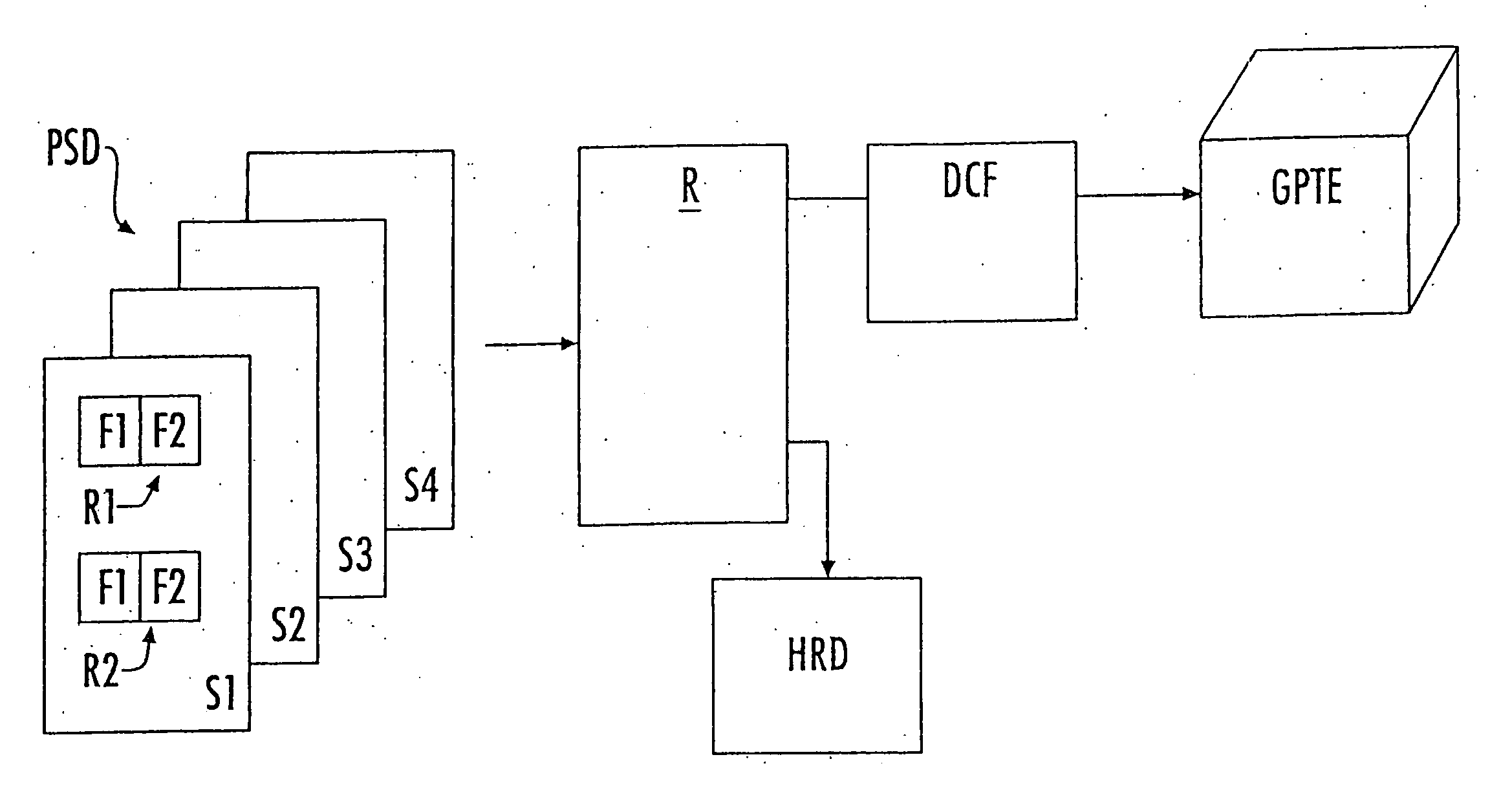
[0012] Referring now to FIG. 1, an example embodiment of the invention is seen in which performance specification document (PSD) is provided in an electronic form in an electronic document mark-up language (for example, Standard Generalized Mark-up Language (SGML)). According to one specific embodiment of the invention, electronic document PSD is in the Extensible Mark-up Language (XML). A specific advantage of the XML embodiment is that XML uses tags only to delimit pieces of data and leaves the interpretation of the tag completely to the application reading the data. According to an alternative embodiment, the electronic performance specification document (PSD) comprises a Hyper-Text Mark-up Language (HTML) document.

[0013] As seen in FIG. 1, the performance specification document includes data in fields (for example, F1 and F2), contained in records (R1 and R2)). The various records and fields of the performance specification document are included in various sections S1-S4. The s...


PUM


Abstract

A system and method for configuration of general purpose test equipment is provided. According to various examples of the invention, performance specification documents in electronic form are input using mark-up language and a mark-up language reader converts the performance specification document into, selectively, a human readable document and a delimited configuration file for input into configurable test equipment having a common object request broker architecture.

Description

CROSS-REFERENCE TO RELATED APPLICATIONS [0001] This application is a continuation of application Ser. No. 11 / 109,295, filed Apr. 19, 2005, which is a continuation of application Ser. No. 10 / 005,639, filed Dec. 4, 2001, to which the instant application claims priority.BACKGROUND [0002] Electronic systems must be tested. Failure of such systems during operation is considered to be catastrophic in many situations (for example, space-craft and missiles). Expensive suites of test equipment have been developed to test complex, high-value electronic systems. These test systems are matched to the design of the system to be tested. Therefore, the test equipment development cannot start until the system to be tested is far down the design and development road, and the amount of time available to develop the test equipment is very short. In addition, inevitable changes to the design of the complex system to be tested, after test equipment development, result in a high cost to modify the test e...

Claims


Application Information

Patent Timeline
Patent Type & Authority Applications(United States)
IPC IPC(8): G06F11/00G06F11/22G06F17/22
CPCG06F11/2273G06F17/2264G06F11/263G06F40/151
Inventor SAUNDERS, JIMMY D.
Owner SAUNDERS JIMMY D
Learn More