Engine load control for hydrostaticaly driven equipment

a technology of hydrostatic or hydraulic drive and load control, which is applied in the direction of picking devices, agricultural tools and machines, picking devices, etc., can solve the problems of crop damage, crop damage, crop damage, and inefficient use of the machine, so as to reduce crop damage, increase harvest area, and reduce crop loss

Inactive Publication Date: 2008-02-14
HELFRICH JAMES C +1
View PDF8 Cites 21 Cited by
  • Summary
  • Abstract
  • Description
  • Claims
  • Application Information

AI Technical Summary

Benefits of technology

[0020]It is another object of the invention to reduce crop damage due to over thrashing of the crop.
[0021]It is another object of the invention to reduce crop loss do to underlaoding of the harvester.
[0022]It is another object of the invention to increase area harvested by maintaining the maximum speed for the crop conditions.
[0023]It is another object of the invention to reduce operator skill level requirements.
[0024]It is another object of the invention to produce crops acceptable to the pharmaceutical industry through greatly increased crop quality.
[0025]In accordance with the present invention, there is provided a harvester load control that will increase the efficiency of the harvester and its operator by providing a control unit that monitors minute engine RPM changes caused by varying crop and transport load effects, automatically adjusting the harvesters ground speed to provide a consistent operational RPM including thrashing, separating and other conditioning services.

Problems solved by technology

All of these conditions affect the way the harvesting machine process the crop.
In conditions where the crop suddenly increases in volume, the combine will not process all of the crop causing some of it to be lost out of the back into the field and an other portion to bypass the holding tank to be reprocessed which further compounds the problem.
In other circumstances the crop my be lighter in yield which creates a situation where when the machine is adjusted to handle heavier crop can cause the crop to be blown out the rear of the machine by the fans used for cleaning.
Varying crop yields and harvesting conditions make it difficult for the harvester operator to adjust the machine.
This makes for greater crop loss, crop damage and inefficient use of the machine.
As the crop lightens the machines engine RPM's accelerate often furthering the problems just discussed. if the machine is over loaded the engine RPM's drop resulting in the slowing of the machines thrashing and separating systems adversely affecting their performance.
The operator cannot detect the tens of thousands of varying conditions he encounters throughout the day and even if he could he is unable to instantly predict the correct change and make that change.
Because of these issues operators and harvesting equipment is often less than efficient resulting in lost crop, lost quality, lost efficiency of labor fuel and more damage to the machine.
When sudden crop changes occur that can actually slug the harvester resulting in a sudden drop in RPM the harvester can actually become plugged.
This plugging of the machine always results in lost productivity and sometimes results in damage to the machine or danger to the operator.
Other solutions do not take in consideration that the human operator is both too slow and too distracted to respond to manual warning signals.
Any operator concentrating for a warning signal, which would occur nearly constantly in fields with varying conditions, would soon become fatigued and confused.
They do not free up the operator for more important and controllable occurrences in or out of the harvesting machine that are a fact of operator life in a harvester.
Soft ground will provide a greater load than hard ground because of tire sink and traction loss.
Boost pressure is also adversely affected because of conditions that are unique to it.
Garvey provides no safety measures for over speed or for protecting an operator if the target RPM is reached.
The unit is not programmable making it difficult for an operator to set and operate the system.

Method used


Image

  • Engine load control for hydrostaticaly driven equipment
  • Engine load control for hydrostaticaly driven equipment
  • Engine load control for hydrostaticaly driven equipment

Examples


Embodiment Construction

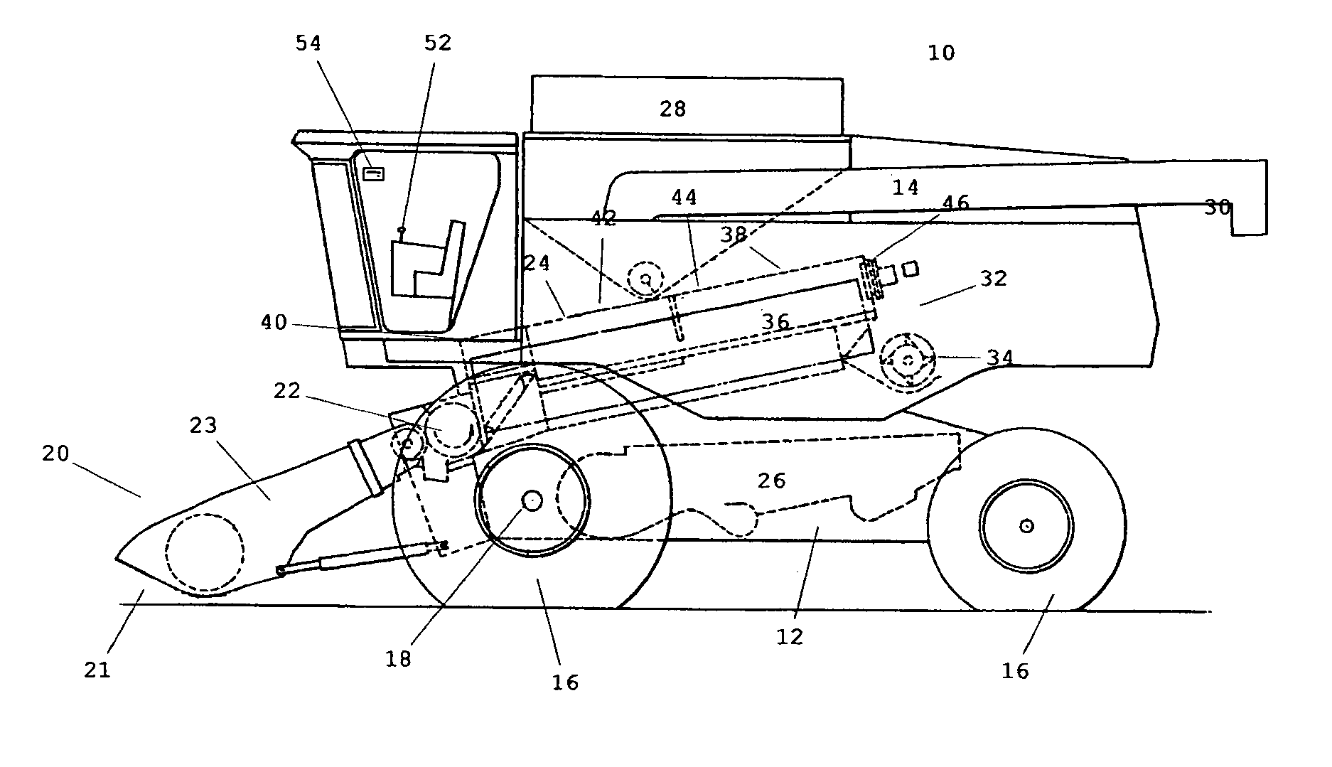
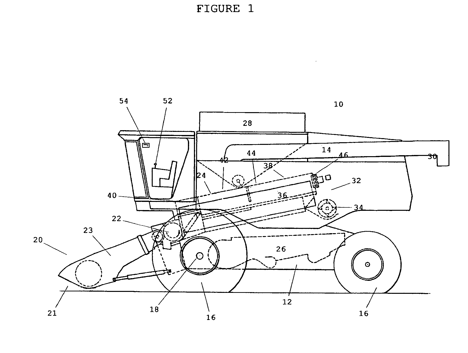
[0032]FIG. 1 is a left elevation view of a combine 10 type harvester.

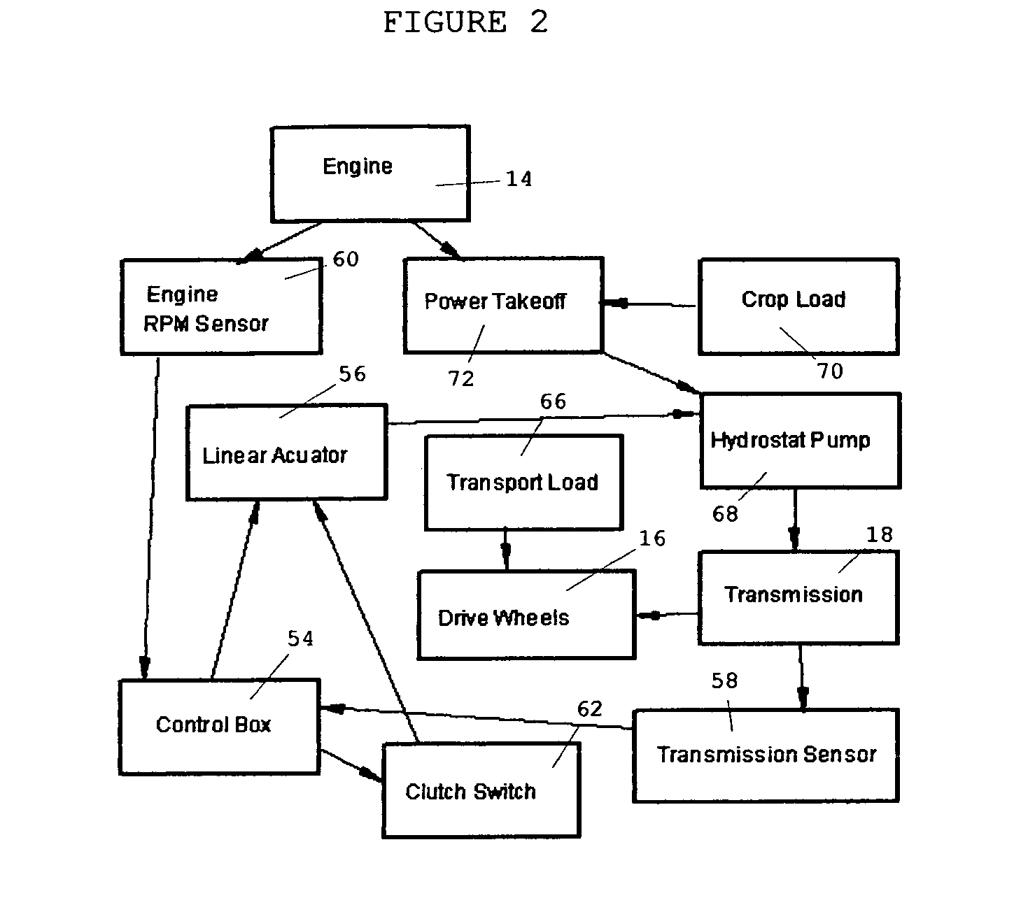
[0033]FIG. 2 is a schematic perspective view of a harvester load effects.

[0034]FIG. 3 is a schematic perspective view of a load control operational flow.

[0035]FIG. 4 is a schematic perspective view of a load control and its components.

[0036]Referring to FIG. 1, therein is shown an agricultural harvester comprising a main frame 12 supported for movement by a wheel structure including drive wheels 16 driven by a hydrostatic transmission 18. The wheel structure depicted could include or be composed of ground engaging tracks or multiples of wheels 16 other than shown.

[0037]A vertically adjustable header or harvesting platform 20 with a cutter bar 21 is used for cutting a standing crop and directing cut material further processing. FIG. 1 depicts one type of harvester known as a combine 10 which includes crop processing features such as the feeder house 23 that is pivotally connected to the frame 12 and includes a conve...


PUM


Abstract

A harvester load control that increases the efficiency of the harvester and its operator by providing a automatic control unit that monitors minute engine RPM's caused by varying crop and transport load effects, automatically adjusting the harvester's ground speed to provide a consistent operational RPM including thrashing, separating and other conditioning services.

Description

RELATED APPLICATIONS[0001]The present application is related to U.S. Pat. No. 4,458,471, issued Jul. 10, 1984, by Herwig, included by reference herein.[0002]The present application is related to U.S. Pat. No. 4,727,710, issued Mar. 1, 1988, by Kuhn, included by reference herein.[0003]The present application is related to U.S. Pat. No. 6,591,591, issued Jul. 15, 2003, by Coers, included by reference herein.[0004]The present application is related to U.S. Pat. No. 6,941,736, issued Oct. 13, 2005, by Freeman, included by reference herein.[0005]The present application is related to U.S. Pat. No. 4,542,802, issued Sep. 24, 1985, by Garvey, included by reference herein.FIELD OF THE INVENTION[0006]The present invention relates to an engine load control and, more particularly, to a load control for hydrostatically or hydraulically driven equipment maintaining a consistent and selectable engine RPM under various loads.BACKGROUND OF THE INVENTION[0007]Combines and other harvesting equipment e...

Claims


Application Information

Patent Timeline
Patent Type & Authority Applications(United States)
IPC IPC(8): A01D41/127
CPCA01D41/127
Inventor HELFRICH, JAMES C.KUCHAR, GEORGE J.
Owner HELFRICH JAMES C
Why Eureka
Try Eureka