Moisture indicator

a technology of moisture indicators and indicators, applied in the field of moisture indicators, can solve the problems of affecting the color affecting the accuracy of the display part,

Inactive Publication Date: 2008-02-14
ESSEN TECH
View PDF18 Cites 19 Cited by
  • Summary
  • Abstract
  • Description
  • Claims
  • Application Information

AI Technical Summary

Benefits of technology

[0014]It is an object of the present invention to provide a moisture indicator for allowing a use...

Problems solved by technology

In case the refrigerant containing moisture circulates the inside of the refrigeration system, the refrigeration efficiency may be dropped and devices may be corroded.
Moreover, the whole system can be damaged severely due to the moisture.
In the conventional moisture indicator, it is difficult to discriminate the color of the display part, because the display part has too small size and soaks in the refrigerant with a low degree of...

Method used


Image

  • Moisture indicator
  • Moisture indicator
  • Moisture indicator

Examples


Embodiment Construction

[0034]Referring now to attaching the drawings, the moisture indicator according to an embodiment of the present invention will be described in detail. It is noted that like parts are designated by like reference numerals throughout the accompanying drawings.

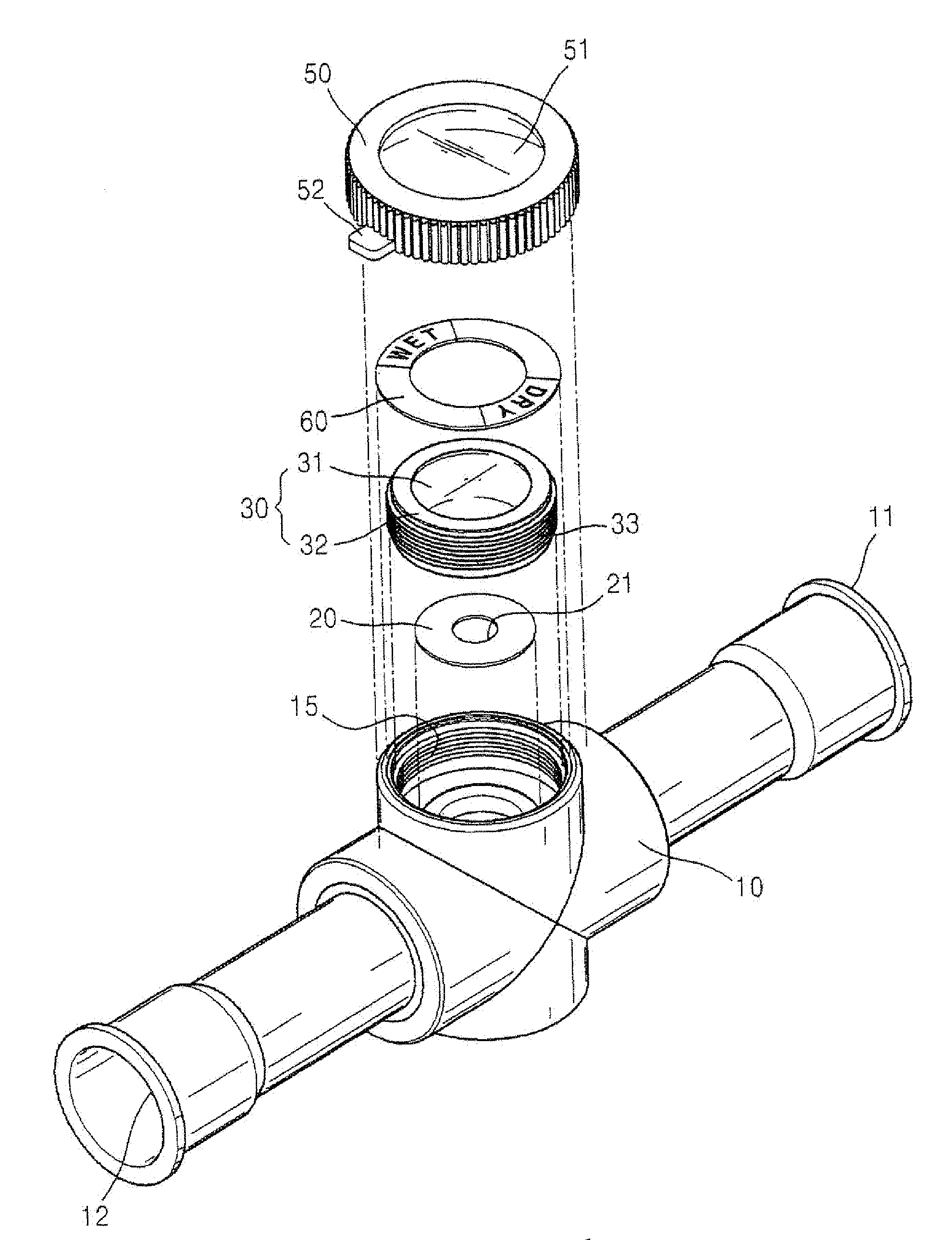
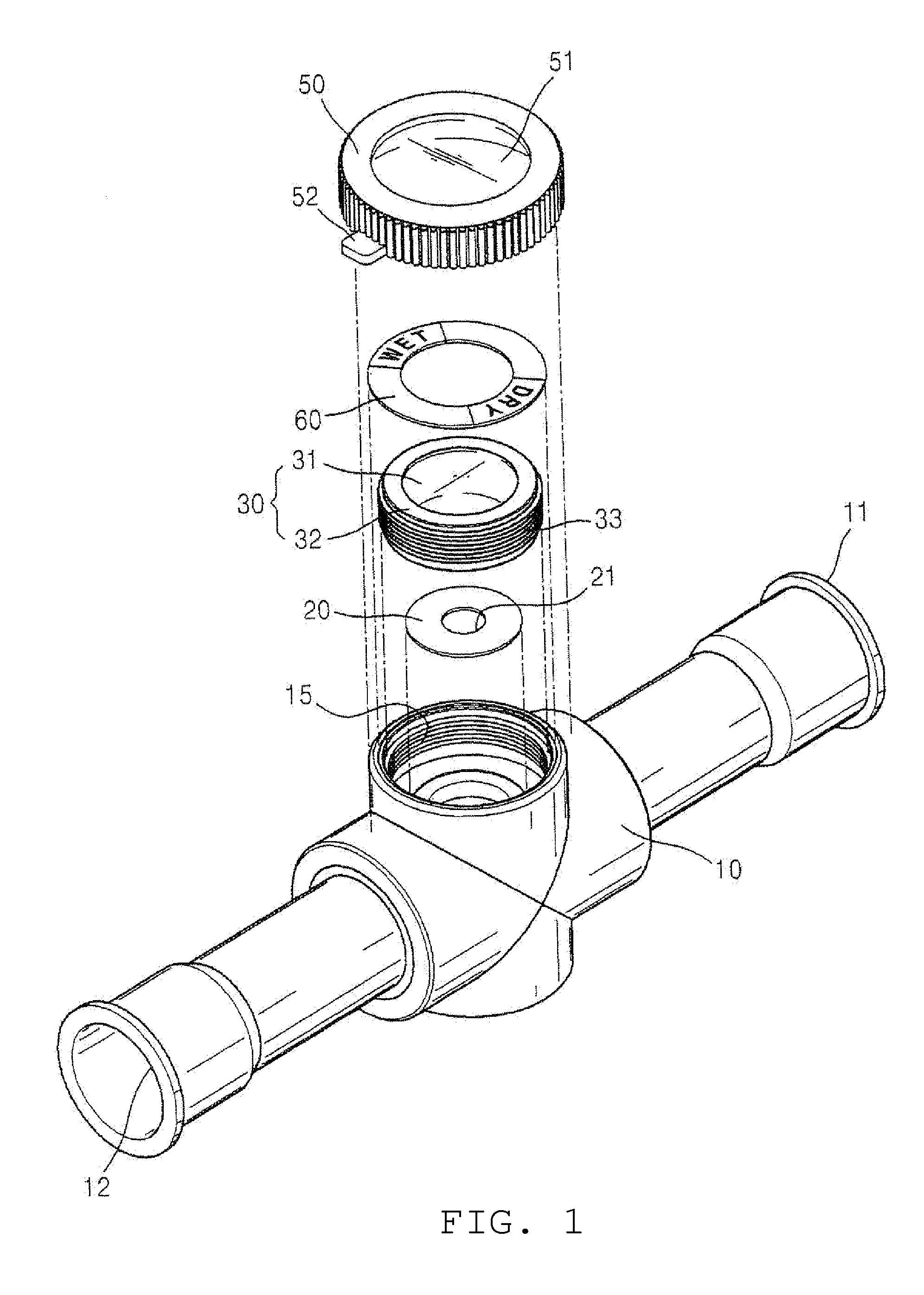
[0035]As shown FIGS. 1 and 2, the moisture indicator of the present invention comprises a body 10, a display member 20, a lens assembly 30, a sealing means (not shown), a lens cap 50, and an exemplification paper 60.

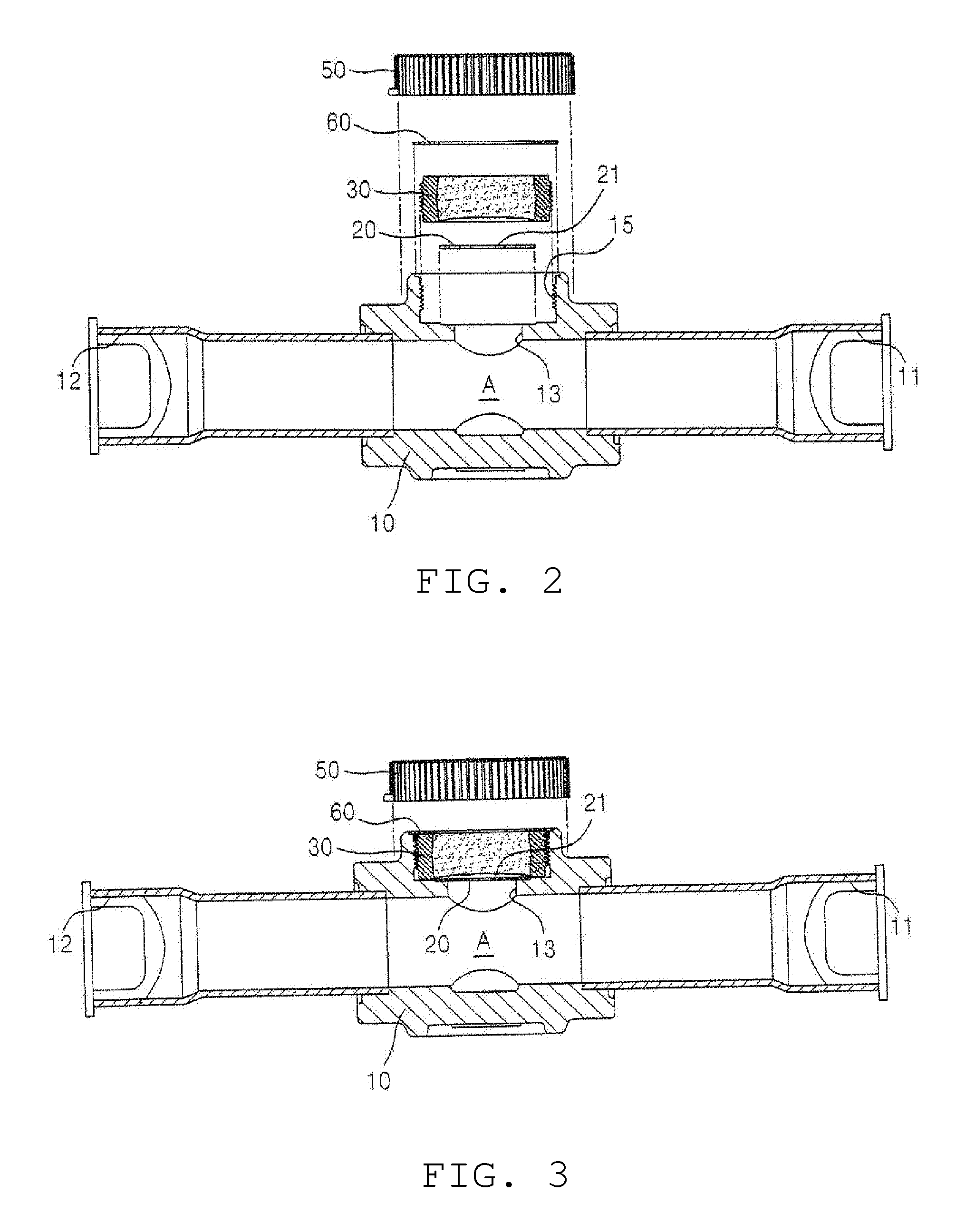
[0036]The body 10 for containing refrigerant 1 has an inlet 11 for introducing the refrigerant 1, an outlet 12 for exhausting the refrigerant 1, an opening 13 for coupling the display member 20 and the lens assembly 30. The refrigerant 1 flows in the containing space A of the body 10.

[0037]The inlet 11 is formed in one end of the body 10 and an outlet 12 is formed in the other end of the body 10. The opening 13 is formed to open upward from the body 10 between the inlet 11 and the outlet 12, and a receiving groove 14 ...


PUM


Abstract

A moisture indicator for a refrigeration system. The moisture indicator includes a body for retaining refrigerant. The body includes an inlet, an outlet and an opening. A display member covers the opening of the body. An inner side of the display member contacts with the refrigerant. A lens assembly displays the color of the display member to the naked eye. The lens assembly is arranged on a receiving groove formed at the outside of the display member. The lens assembly is sealed within the receiving groove. The moisture indicator allows a user accurately to identify the color of the display member without disturbing the flow of the refrigerant. It also allows the user accurately to determine when to replace a filter drier and when to supplement the refrigerant.

Description

BACKGROUND OF THE INVENTION[0001](1) Field of the Invention[0002]The present invention relates to moisture indicators and particularly to an indicator to be used in a refrigeration system to show a moisture content of refrigerant.[0003](2) Description of the Related Arts[0004]Generally, a refrigeration system, such as an air conditioner or a refrigerator, performs cooling and freezing operation by absorbing heat from the area to be cooled and giving out heat to the outside.[0005]In a typical refrigeration system, cooling is achieved by the circulation of refrigerant in a closed system. The refrigerant is compressed to a high pressure by a compressor and is condensed through the condenser. Then the condensed refrigerant passes through an expansion valve into an evaporator where it evaporates and collects heat from the area to be cooled. From the compressor, the refrigerant is routed back to the condenser and the cycle repeats.[0006]In the refrigeration system, moisture may be spontan...

Claims


Application Information

Patent Timeline
IPC IPC(8): F25B49/00F25B47/00
CPCF25B41/006G01N19/10
Inventor CHO, SI-NAMLEE, SANG-BONGKIM, GI-SIK
Owner ESSEN TECH
Why Eureka
Try Eureka