System and method for transferring calibration data

a technology of calibration data and transfer method, applied in the field of autocalibration label, can solve the problems of inability to enter sensor information via the calibration chip, return an error, and inability to accurately measure the accuracy of the calibration information

Active Publication Date: 2008-02-14
ASCENSIA DIABETES CARE HLDG AG
View PDF13 Cites 111 Cited by
  • Summary
  • Abstract
  • Description
  • Claims
  • Application Information

AI Technical Summary

Problems solved by technology

These methods suffer from the disadvantage of relying on the user to enter the calibration information, which some users may not enter at all or may input incorrectly.
In this event, the test sensor may use the wrong calibration information and thus return an erroneous result.
Where a calibration chip is contained within the sensor packaging, the calibration chip can be easily lost or misplaced, resulting in an inability to enter the sensor information via the calibration chip.
Simpler forms of such a cartridge, where sensors are sealed in individual compartments, generally provide little or no flexibility to vary the number of sensors that can packaged and the maximum is limited by the maximum acceptable cartridge size.
Cartridges with sensors stacked within a common compartment can support larger and potentially variable numbers of stored sensors, but providing a good environmental seal after the first sensor is extracted is difficult, has associated technical complexity and costs associated with automated sensor access, and, in simpler forms, may be inflexible in the number of sensors that can be packaged.

Method used


Image

  • System and method for transferring calibration data
  • System and method for transferring calibration data
  • System and method for transferring calibration data

Examples


embodiment a

Alternative Embodiment A

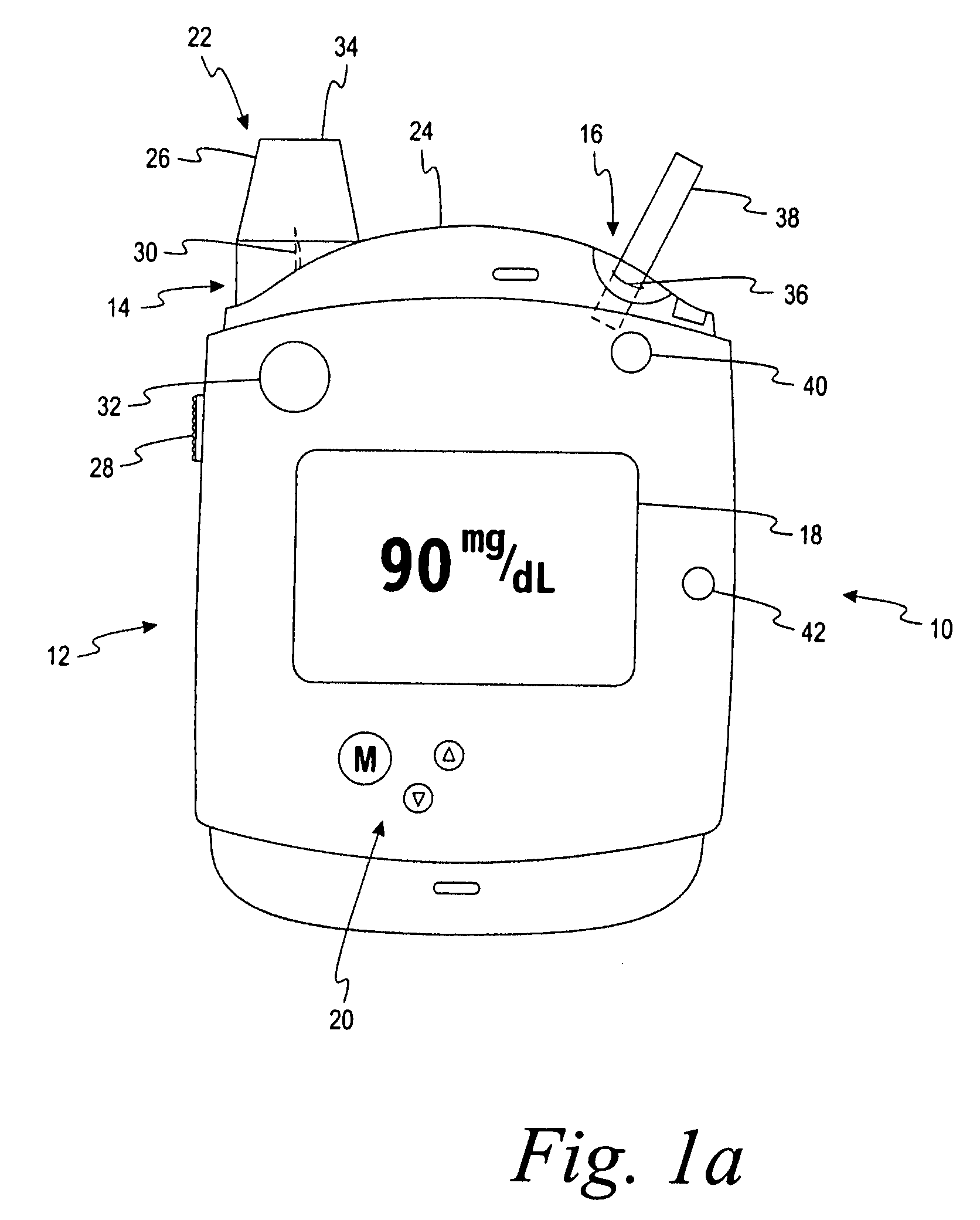
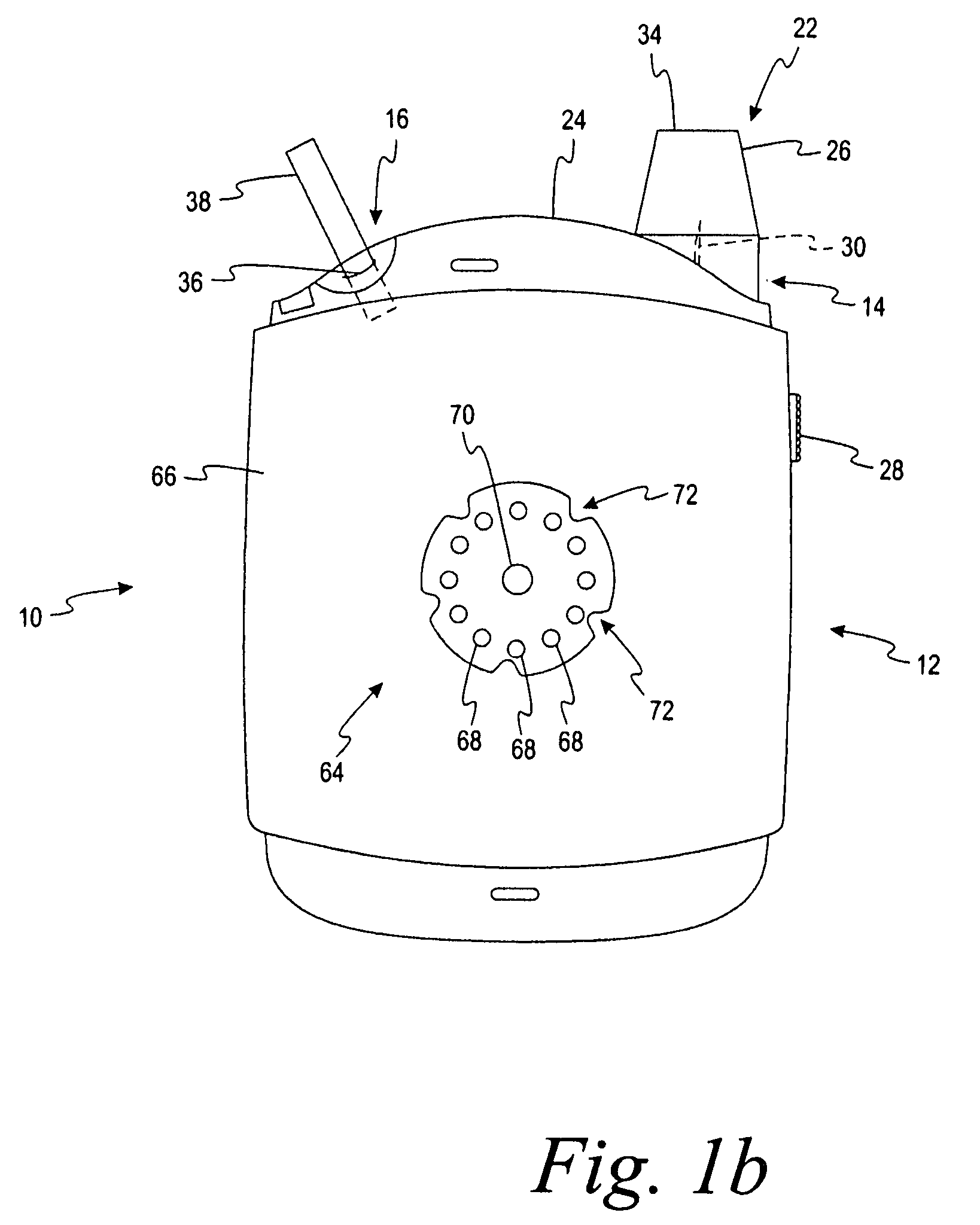
[0094]A test system for determining an analyte concentration in a fluid sample, comprising:

[0095]a sensor container having a base and a lid, the sensor container being adapted to enclose a plurality of test sensors therein, the sensor container including a calibration label attached thereto, the calibration label including a plurality of electrical contacts located thereon, the electrical contacts being adapted to encode calibration information onto the calibration label; and

[0096]a testing device having an auto-calibration feature externally located thereon, the testing device being adapted to determine the analyte concentration in the fluid sample, the auto-calibration feature including a plurality of calibration elements being adapted to communicate with the plurality of electrical contacts on the calibration label,[0097]wherein the testing device is adapted to determine the calibration information encoded on the calibration label in response to the calibr...

embodiment b

Alternative Embodiment B

[0098]The test system of Alternative Embodiment A, wherein the calibration label is attached to the lid of the sensor container.

embodiment c

Alternative Embodiment C

[0099]The test system of Alternative Embodiment A, wherein the testing device and the auto-calibration feature form a digital electronic circuit.


PUM

PropertyMeasurementUnit
resistanceaaaaaaaaaa

Abstract

A test system comprises a sensor container and a testing device. The sensor container has a base and a lid. The container encloses test sensors therein. The container includes a calibration label attached thereto. The label includes electrical contacts located thereon. The electrical contacts encode calibration information onto the calibration label. The testing device has an auto-calibration feature externally located thereon. The testing device is adapted to determine the analyte concentration in a fluid sample. The auto-calibration feature includes calibration elements that communicate with the electrical contacts on the calibration label. The testing device is adapted to determine the calibration information encoded on the calibration label in response to the calibration elements engaging the electrical contacts. The encoded calibration information is determined without inserting the sensor container or the calibration label into the testing device.

Description

CROSS REFERENCE TO RELATED APPLICATION[0001]This application claims priority to Application No. 60 / 837,538 filed on Aug. 14, 2006, which is incorporated by reference in its entirety.FIELD OF THE INVENTION[0002]The present invention relates generally to an auto-calibration label used to automatically calibrate instruments or meters that determine the concentration of an analyte. The auto-calibration labels are incorporated onto a package of singulated test strips and an external portion of the instrument or meter is adapted to determine the calibration information from the label.BACKGROUND OF THE INVENTION[0003]The quantitative determination of analytes in body fluids is of great importance in the diagnoses and maintenance of certain physiological abnormalities. For example, lactate, cholesterol and bilirubin should be monitored in certain individuals. In particular, it is important that diabetic individuals frequently check the glucose level in their body fluids to regulate the gluc...

Claims


Application Information

Patent Timeline
Patent Type & Authority Applications(United States)
IPC IPC(8): G01N27/00
CPCG01N33/48771Y10T436/110833Y10T436/104998Y10T436/10Y10T436/115831
Inventor SCHELL, ROBERT D.
Owner ASCENSIA DIABETES CARE HLDG AG
Why Eureka
Try Eureka