Vehicle air-conditioning system

a vehicle air conditioner and air conditioning technology, applied in the field of vehicle air conditioning systems, can solve the problems of reducing the air-conditioning capability of the vehicle air-conditioning system, and achieve the effects of accurate temperature detection, reduced size, and high accuracy

Inactive Publication Date: 2008-02-14
KEIHIN CORP
View PDF4 Cites 11 Cited by
  • Summary
  • Abstract
  • Description
  • Claims
  • Application Information

AI Technical Summary

Benefits of technology

[0010]It is a major object of the present invention to provide a vehicle air-conditioning system which is capable of accurately d

Problems solved by technology

However, the position or layout change would lower the accuracy of the temperature of the air measured by the temperature sensor 7 or prevent the air-mixing door

Method used


Image

  • Vehicle air-conditioning system
  • Vehicle air-conditioning system
  • Vehicle air-conditioning system

Examples


Embodiment Construction

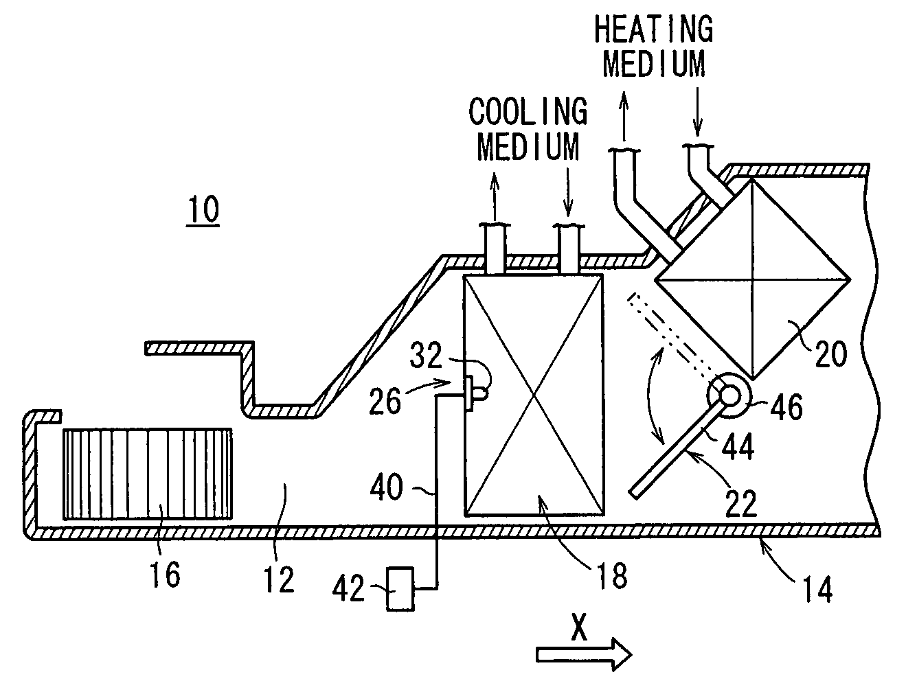
[0023]As shown in FIG. 1, a vehicle air-conditioning system 10 according to an embodiment of the present invention has a duct 14 defining a passage 12 therein for discharging temperature- and humidity-regulated air into the passenger's compartment of a vehicle. The vehicle air-conditioning system 10 includes a blower 16 disposed in the duct 14 at a position upstream with respect to the direction in which air flows in the passage 12, i.e., in the direction indicated by the arrow X, and an evaporator (cooling heat exchanger) 18 disposed in the duct 14 downstream of the blower 16. A heater core (heating heat exchanger) 20 is in the duct 14 downstream of the evaporator 18. An air-mixing mechanism 22 for mixing cool air and hot air with each other is mounted in the duct 14 on an inlet side of the heater core 20.

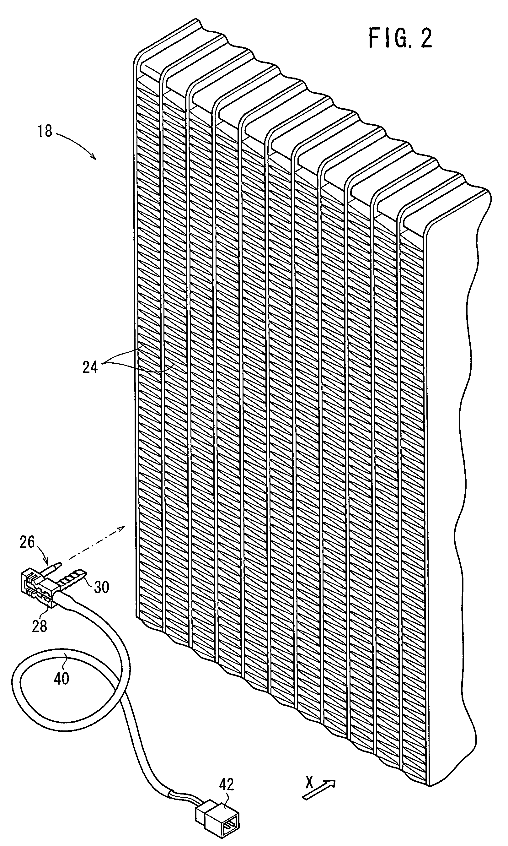
[0024]As shown in FIG. 2, the evaporator 18 includes fins 24 in which a coolant (temperature-regulating medium) flows. The evaporator 18 evaporates the coolant by allowing heat to...


PUM


Abstract

A vehicle air-conditioning system includes a duct housing therein an evaporator, an air-mixing mechanism, and a heater core that are successively arranged along the direction in which air is delivered by a blower to flow through the duct. A temperature sensor for detecting the temperature of the evaporator is disposed upstream of the evaporator with respect to the direction in which the air flows through the duct. The temperature sensor has at least a portion inserted in the evaporator.

Description

BACKGROUND OF THE INVENTION[0001]1. Field of the Invention[0002]The present invention relates to a vehicle air-conditioning system having a duct for discharging regulated air into the passenger's compartment of a vehicle, the duct housing therein a heat exchanger for performing heat exchange between air and a temperature-regulating medium which flow in the duct.[0003]2. Description of the Related Art[0004]Usually, vehicle air-conditioning systems include a temperature sensor for measuring the temperature of air immediately after the air has passed through a heat exchanger such as an evaporator or the like for the purpose of preventing the heat exchanger from being frozen.[0005]For example, as shown in FIG. 8 of the accompanying drawings, a vehicle air-conditioning system disclosed in Japanese Laid-Open Patent Publication No. 2003-300410 has a casing 2 defining therein a passage 1 for discharging regulated air into the passenger's compartment of the vehicle. The vehicle air-condition...

Claims


Application Information

Patent Timeline
IPC IPC(8): F25B29/00F25B49/00
CPCB60H1/00792
Inventor YAMAKAWA, HIROSHI
Owner KEIHIN CORP
Why Eureka
Try Eureka