Carry Device

Inactive Publication Date: 2008-02-14
BUILT NY
View PDF24 Cites 79 Cited by
  • Summary
  • Abstract
  • Description
  • Claims
  • Application Information

AI Technical Summary

Benefits of technology

[0024]Another proposed object of an alternative embodiment the present invention is to provide a convenient and attractive carry device that allows economical production and optionally reuse or recycling.
[0025]Another proposed object of an alternative embodiment of the present invention is to provide a convenient device for receiving items to be carried that includes at least one inner cavity or bladder for inflation or storage of a pressure or a temperature transfer medium, whereby the received items are restrained from moving without crushing or optionally maintained at a desirable temperature during transport.
[0026]Another alternative object of one embodiment of the present invention is to provide an inflatable carry device enabling a substantially common pressure application along a pressure contact surface of an item being transported without damaging pressure variants.
[0027]Another alternative object of

Problems solved by technology

Thus, packaging device 700 is well suited for shipping rigid electronic or other hard-bodied products, but is ill-suited to contain and preserve non-rigid items in a non-crushed manner, and cannot protect such items from moisture or air damage due to air gaps 729 and lack of a seal around the items.
What is also not

Method used


Image

  • Carry Device
  • Carry Device
  • Carry Device

Examples


first embodiment

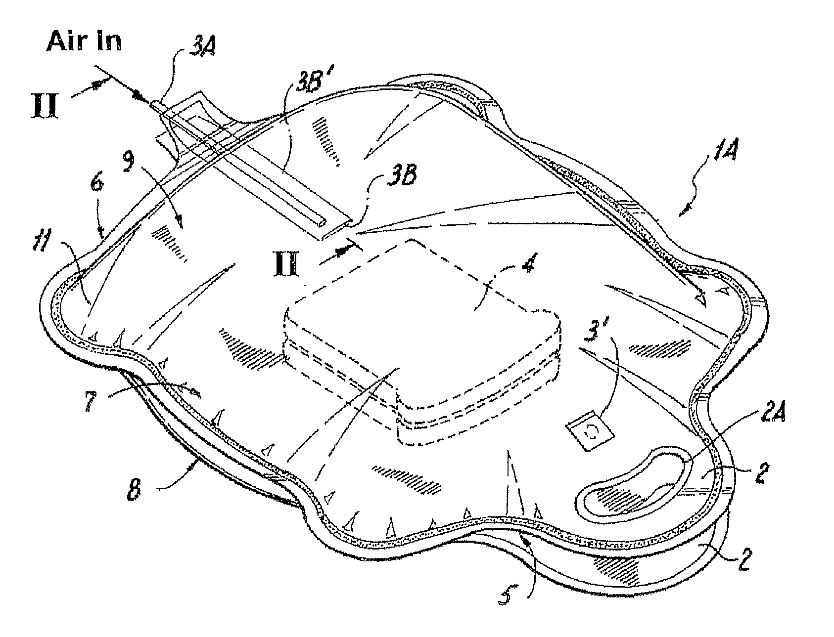
[0096]Referring now to FIGS. 7 through 12, a carry assembly 1A is provided including a pair of separable carry handles 2, having holes 2A providing easy access to a defined inner opening 5 for receiving carry items 4 (here food items) into an inner pouch member (shown later).

[0097]Top and bottom members 7, 8 form an outer surface of an outer pouch 10 having an outer perimeter 6 proximate seam 6′. An inflation access port 3 and deflation access port 3′ provides ready access to at least one access cavity 200 defined between outer pouch 10 and the inner pouch member 9 having inner pouch walls 9′ and 9″. During use, a user inserts items 4 (shown as a sandwich) in direction A into inner opening 5 and blows into access port 3 via a straw 3A filling the bounded cavity 200 with air along air flows 9B to a desired inflation pressure, causing outer pouch 10 of carry assembly 1A to expand and assume a shape defined by outer seals 6′ and outer perimeter 6. Such a shape and pressure provides sec...

third embodiment

[0109]As noted in the third embodiment, inner pouch 9A extends substantially to outer perimeter 6 and outer seam 6′ enabling a very simplified and speedy construction and dividing and bisecting the inner region of outer pouch 10C into substantially two halves. As noted in FIG. 17, a bottom portion of inner pouch side walls 9C′, 9C″ proximate inflation portal 3, are in a sealing connection and are not open to the inner pouch opening. An air passage hole 9″ is punched through this sealed connection region allowing air passage between both sides of the inner region of outer pouch 10C without causing deflation into inner pouch 9C.

[0110]In the embodiment shown construction may be substantially simplified while retaining the benefits inherent in the present invention in an alternative embodiment. As described, the present carry device 1C includes four sheets of seamed material and improves both the stability of carry device 1C while improving appearance to a select segment of the market f...

sixth embodiment

[0118]In this sixth embodiment of carry device 1F, inner pouch member is retained on position between two opposing end fixture regions, namely handles 2F / opening 5F, and the region near inflation port 3F. Thus, the present embodiment securely positions inner pouch member 9F in a manner that does not restrain the planer surfaces of inner pouch side walls 9F, 9F′ and retains inner pouch member 9F distant from outer side walls 7F, 8F during inflation, thereby increasing cushioning while allowing inner pouch member 9F to readily adapt to an item to be carried without irregular pressure concentrations along its outer surface.


PUM


Abstract

In one embodiment a carry device includes a first inner carry pouch made from a first material and an outer bounding pouch or layer made from a second material defining at least one cavity therebetween. An access port may include a release and inflation actuator and provides volumetric access to the at least one cavity allowing passage of a pressurizing atmosphere or temperature effecting medium, or combination thereof. A sealable access is provided, and a common pressure is applied to an outer uniform-pressure region of a non-rigid or rigid item being carried thereby preventing damage and crushing thereof through high contact pressure gradients. In another embodiment handles are inflatable to aid sealing the inner carry pouch and provide a comfortable grip.

Description

CROSS REFERENCE TO RELATED APPLICATIONS[0001]This application claims priority from U.S. Provisional Application No. 60 / 630,646 filed Nov. 24, 2004, the contents of which are fully incorporated herein by reference.BACKGROUND OF THE INVENTION[0002]1. Field of the Invention[0003]The present invention relates to a carry device. More specifically, the present invention relates to a convenient device for receiving items to be carried that includes at least one inner cavity or bladder for inflation or storage of a pressure or a temperature transfer medium, whereby the received items are restrained from moving.[0004]2. Description of the Related Art[0005]Various attempts have been made to use air pillows or bags in packaging to secure items being shipped. U.S. Pat. Nos. 5,254,074 and 5,339,602 to Landers et al., outline the general processes for forming a series of inflatable air bags and placing those bags in shipping containers for inflation to secure items being shipped. Landers also out...

Claims


Application Information

Patent Timeline
IPC IPC(8): B65D81/15B65D30/26
CPCB65D31/145B65D33/08B65D33/12B65D81/052B65D77/04B65D81/03B65D33/16
Inventor SWARTZ, JOHN R.LOWN, AARON
Owner BUILT NY
Why Eureka
Try Eureka