Cogeneration system
a technology of cogeneration system and cogeneration technology, applied in the direction of machines/engines, lighting and heating apparatus, heating types, etc., can solve the problems of failure to maximize efficiency, and achieve the effect of maximizing heat and power efficiency
- Summary
- Abstract
- Description
- Claims
- Application Information
AI Technical Summary
Benefits of technology
Problems solved by technology
Method used
Image
Examples
fourth embodiment
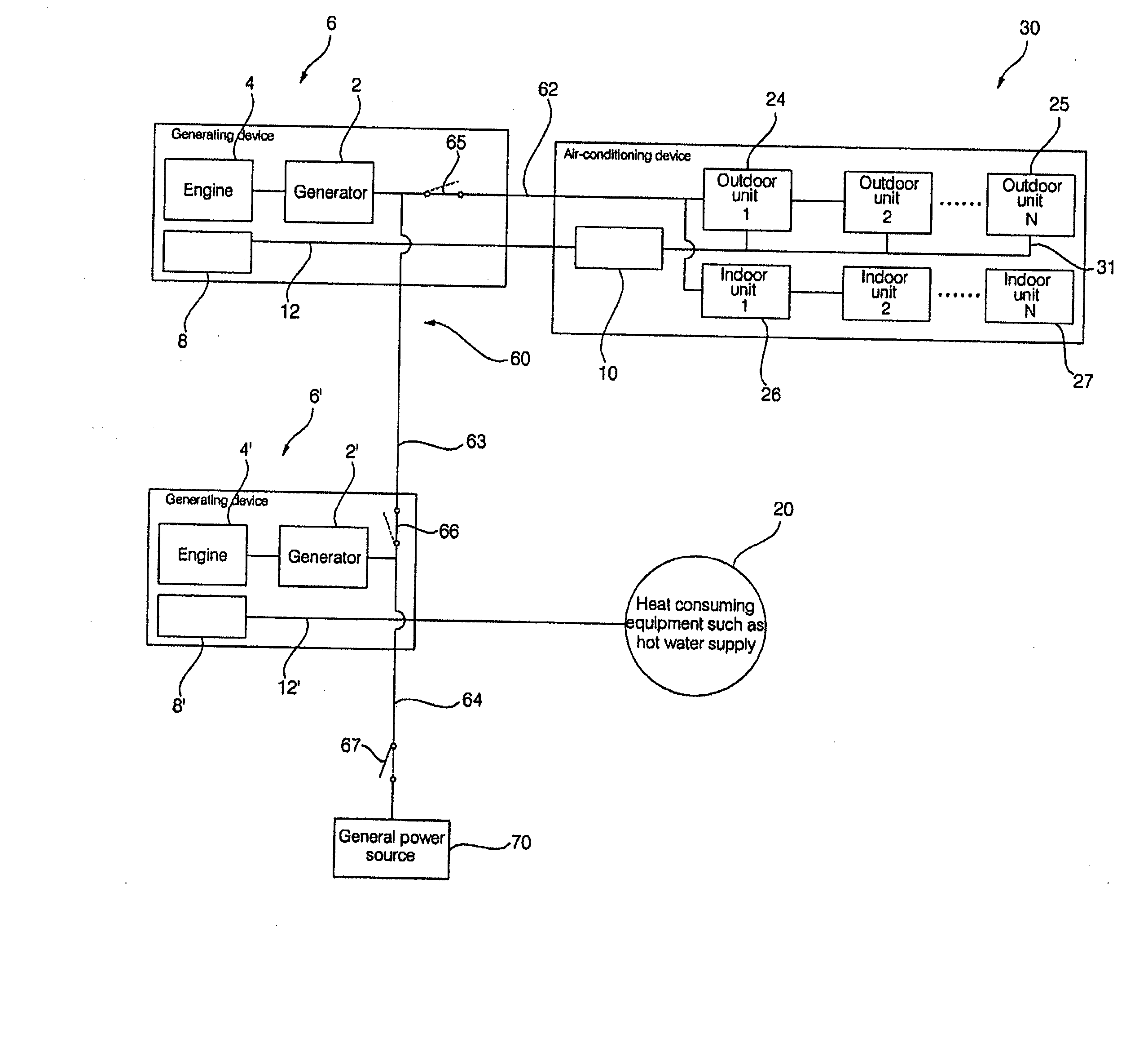
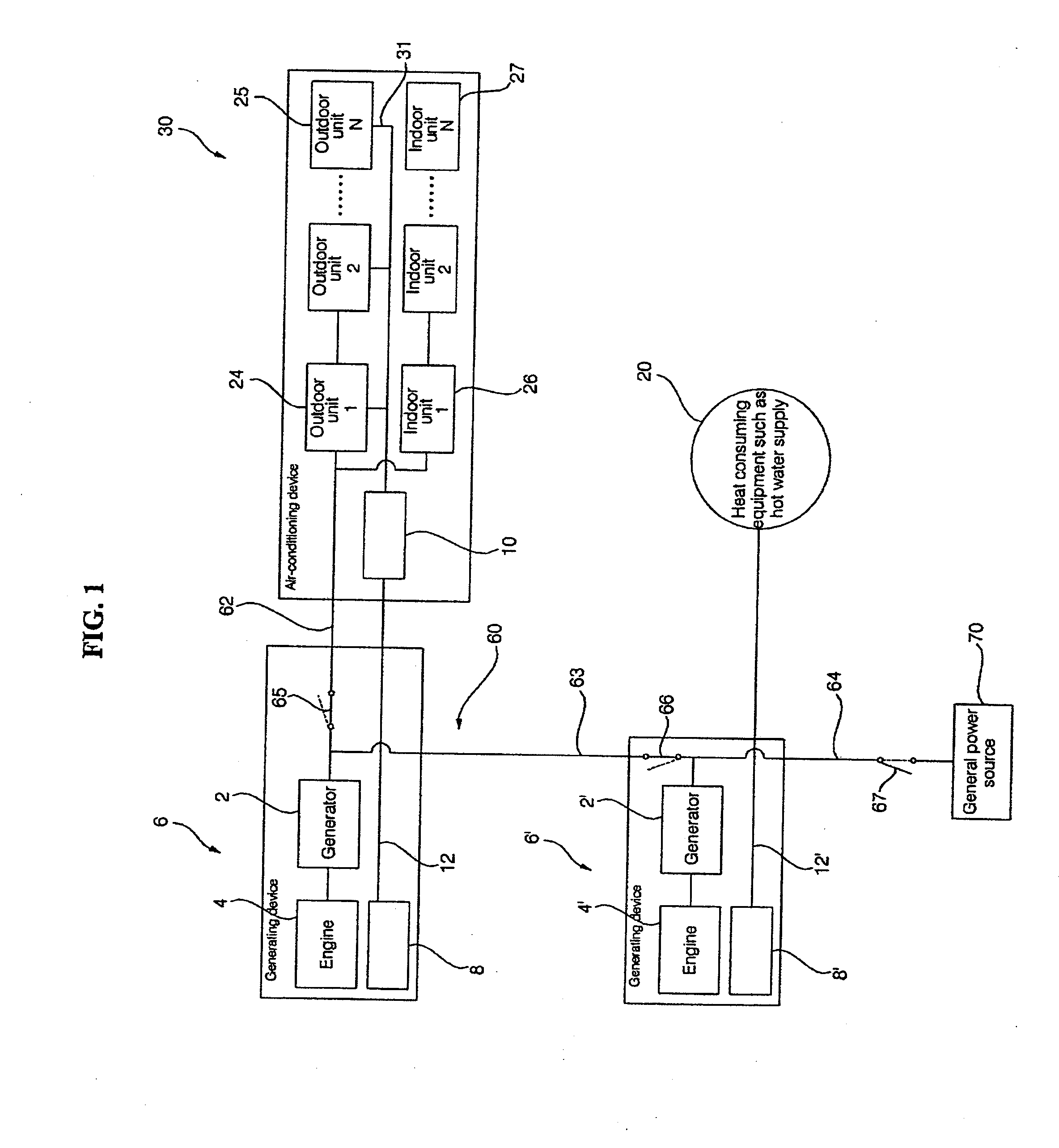
[0114] Referring to the cogeneration system, if the outdoor units 24 and 25 of the air-conditioning devices 30, 40, and 50 are much away from the generating device 6, the heat transfer line 12 and the refrigerant pipe 31 should be installed long, causing a problem that the arrangement of the generating device 6 fails to uniformly distribute heat to the plurality of air-conditioning devices 30, 40, and 50. However, in the cogeneration system according to the present invention, because the heat recovery mechanism 10″ is positioned between the generating device 6 and the air-conditioning devices 30, 40, and 50, the possible imbalance of heat distribution can be resolved.
[0115]FIG. 7 is a view showing a construction of a cogeneration system according to a fifth exemplary embodiment of the present invention.
[0116] In the cogeneration system according to the fifth exemplary embodiment of the present invention as shown in FIG. 7, the plurality of air-conditioning devices 30, 40, and 50 ar...
sixth embodiment
[0123] In the cogeneration system according to the sixth exemplary embodiment of the present invention as shown in FIG. 8, the plurality of generating devices 6 are connected with the plurality of air-conditioning devices 30, 40, and 50, and the heat recovery mechanism 10 is installed in each of the air-conditioning devices 30, 40, and 50. Other construction and operation of the cogeneration system according to the present invention are the same as or similar to those of the cogeneration system according to the fifth exemplary embodiment of the present invention, so the same reference numerals are given and its detailed description will be omitted.
[0124]FIG. 9 is a view showing a construction of a cogeneration system according to a seventh exemplary embodiment of the present invention.
seventh embodiment
[0125] In the cogeneration system according to the seventh exemplary embodiment of the present invention, the plurality of generating devices 6 are connected with the plurality of air-conditioning devices 30, 40, and 50, and the heat recovery mechanism 10″ is separately installed between the generating devices 6 and the air-conditioning devices 30, 40, and 50. Other construction and operation of the cogeneration system according to the present invention are the same as or similar to those of the cogeneration system according to the fifth exemplary embodiment of the present invention, so the same reference numerals are given and its detailed description will be omitted.
[0126] Herein, only the single heat recovery mechanism 10″ can be installed between the plurality of generating devices 6 and the plurality of air-conditioning devices 30, 40, and 50 as shown in FIG. 8, and heat recovery mechanisms can be respectively installed between the generating devices 6 and the air-conditioning ...
PUM
 Abstract
Description
Claims
Application Information
 - R&D
- Intellectual Property
- Life Sciences
- Materials
- Tech Scout
- Unparalleled Data Quality
- Higher Quality Content
- 60% Fewer Hallucinations
Browse by: Latest US Patents, China's latest patents, Technical Efficacy Thesaurus, Application Domain, Technology Topic, Popular Technical Reports.
© 2025 PatSnap. All rights reserved.Legal|Privacy policy|Modern Slavery Act Transparency Statement|Sitemap|About US| Contact US: help@patsnap.com


