Time-of-flight-ranging system and method for calibrating such a system

a time-of-flight ranging and time-of-flight technology, which is applied in the field of time-of-flight ranging systems and a method for calibrating such systems, can solve the problems of small differences in the operation of radio frequency oscillators, difficulty in maintaining a high degree of accuracy over a range of temperatures and operating conditions, and errors in measured distances

Inactive Publication Date: 2008-02-14
SIEMENS AG
View PDF8 Cites 33 Cited by
  • Summary
  • Abstract
  • Description
  • Claims
  • Application Information

AI Technical Summary

Problems solved by technology

When measuring distance using the time of flight method in radar or TDR (time domain reflectometry) based instruments, it is difficult to maintain a high degree of accuracy over a range of temperatures and operating conditions.
There will be variations in the electronic components that lead to errors in the measured distance.
However, as a result of aging or temperature variation in the components, there may be slight differences in the operation of the radio frequency (RF) oscillators or in the pulses (i.e. control signals) that enable the RC oscillators.
In addition, the timebase generator may itself introduce a few picoseconds of error that can add or subtract from the total accumulating error.
While these variations can be minimized by further design enhancements, the design becomes more and more expensive as higher and better accuracy and stability is sought, until the point is reached where it is prohibitively expensive to improve the accuracy any further.

Method used


Image

  • Time-of-flight-ranging system and method for calibrating such a system
  • Time-of-flight-ranging system and method for calibrating such a system
  • Time-of-flight-ranging system and method for calibrating such a system

Examples


Embodiment Construction

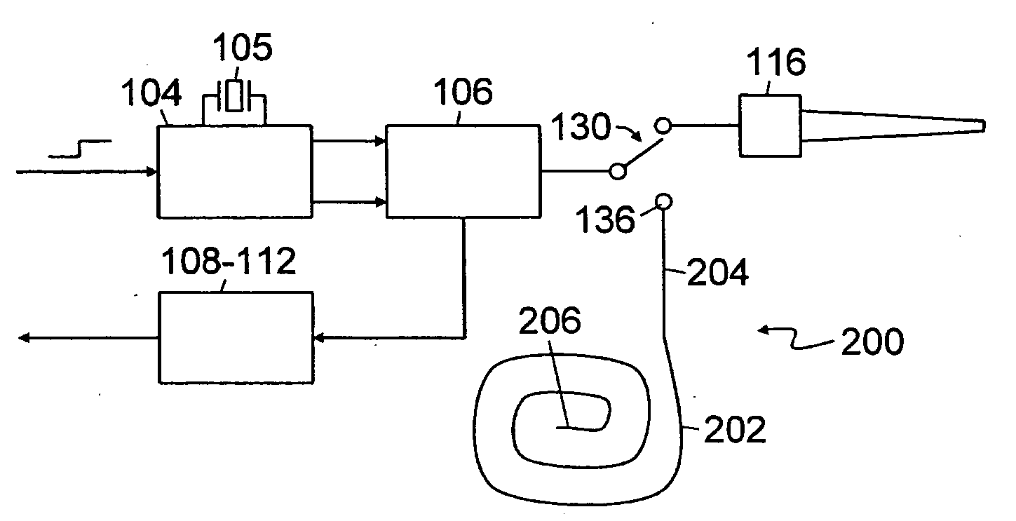
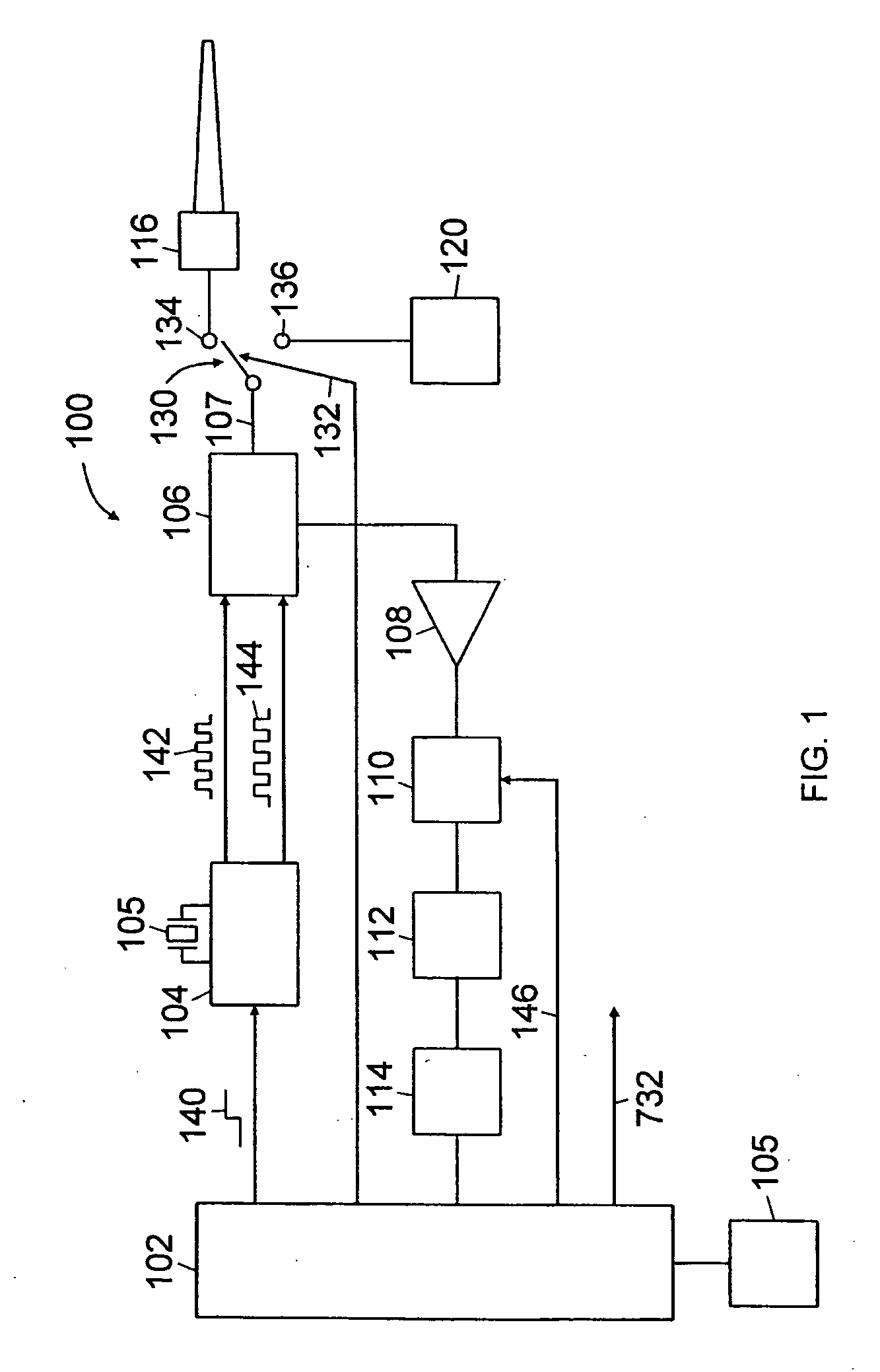
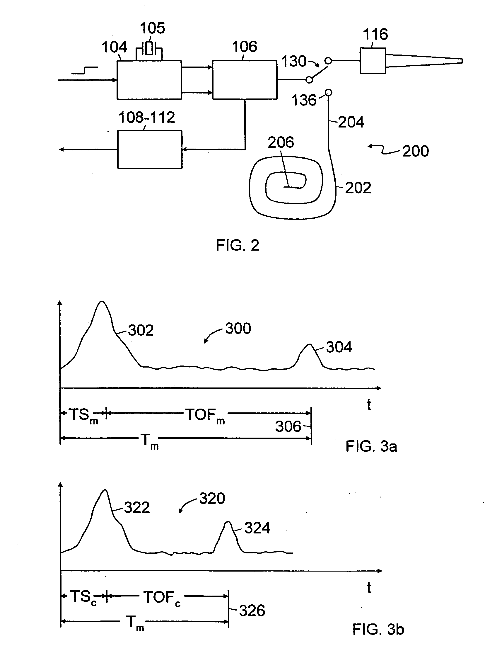
[0027]Reference is first made to FIG. 1 which shows a time-of-flight level measurement device 100. As described, the level measurement device 100 comprises a radar based or a guided wave radar time domain reflectometry (TDR) system. In accordance with one aspect of the present invention, the level measurement device 100 includes an embedded calibration mechanism or module indicated generally by reference 120. As described in more detail below, the embedded calibration module 120 provides the capability to generate internal signals and perform calibration operations to measure errors which may arise in the electronic circuitry due to the effects of temperature drift and / or component drift over time.

[0028]As shown in FIG. 1, the level measurement device 100 comprises a microcontroller or microprocessor 102, a time-base generator 104, a radar transceiver 106, an amplifier 108, a filter module 110, an envelope detector module 112, an analog-to-digital converter 114, a radiating antenna ...


PUM


Abstract

An embedded calibration mechanism and method for a time-of-flight ranging system. The calibration mechanism (200) comprises a channel (202) having known characteristics. Periodically or as part of a calibration function, a pulse is transmitted through the calibration channel (202) and parameters such transmit pulse delay time and apparent velocity are determined. The calibration parameters or measurements are used to calibrate or compensate operation or measurements from the measurement channel.

Description

CROSS REFERENCE TO RELATED APPLICATIONS[0001]This application claims priority of European application No. 05021177.0 EP filed Sep. 28, 2005, which is incorporated by reference herein in its entirety.FIELD OF THE INVENTION[0002]The present invention relates to a time-of-flight ranging system and a method for calibrating such a system.BACKGROUND OF THE INVENTION[0003]Pulse-echo acoustic ranging systems, also known as time-of-flight ranging systems, are commonly used in level measurement applications. Pulse-echo acoustic ranging systems determine the distance to a reflector (i.e. reflective surface) by measuring how long after transmission of a burst of energy pulses the echo or reflected pulses are received. Such systems typically use ultrasonic pulses or pulse radar or guided radar signals.[0004]Pulse-echo acoustic ranging systems generally include a transducer and a signal processor. The transducer serves the dual role of transmitting and receiving the energy pulses. The signal proc...

Claims


Application Information

Patent Timeline
Patent Type & Authority Applications(United States)
IPC IPC(8): G01S7/40G01S13/08
CPCG01S7/4052G01S2007/4065G01S13/10G01S7/4065
Inventor LYON, GEORGE QUINTON
Owner SIEMENS AG
Why Eureka
Try Eureka