

Display device and driving method thereof
- Summary
- Abstract
- Description
- Claims
- Application Information
AI Technical Summary
Benefits of technology
Problems solved by technology
Method used
Image

Examples
first embodiment
[0034] Referring to the figures, the following description will discuss an embodiment in accordance with the present invention.
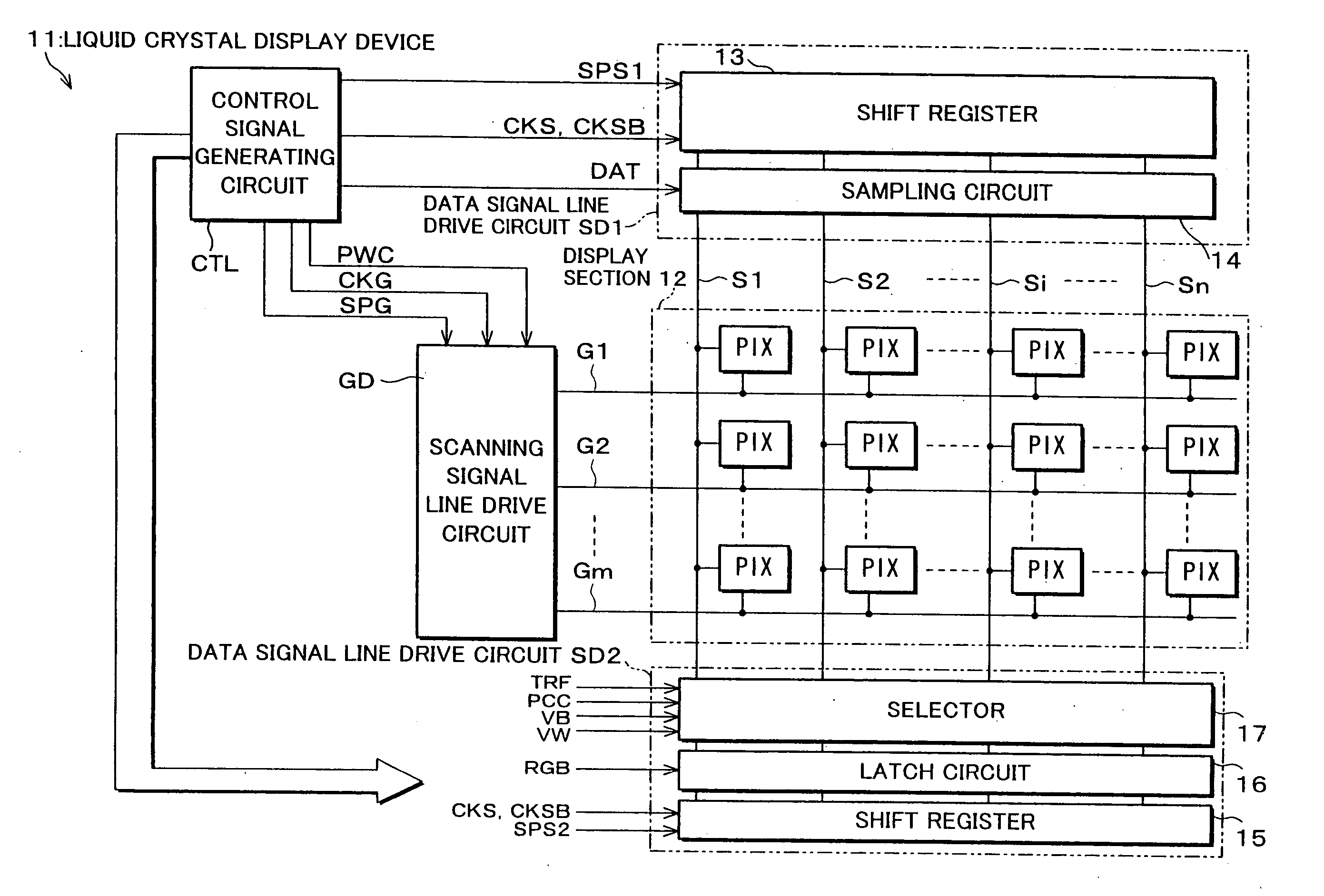
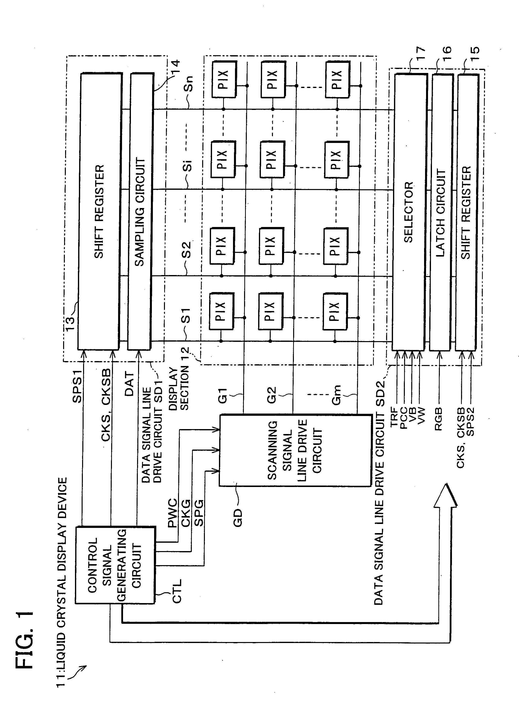
[0035]FIG. 1 illustrates an embodiment of a display device in accordance with the present invention, and is a block diagram illustrating an electrical arrangement of a liquid crystal display device 11. This liquid crystal display device 11 is a TFT active matrix liquid crystal display device, and roughly includes: a display section 12; a scanning signal line drive circuit GD; a data signal line drive circuit SD1; a data signal line drive circuit SD2; and a control signal generating circuit CTL.
[0036] The display section 12 is provided with: a plurality of scanning signal lines G1, G2, . . . , Gm (collectively termed G); data signal lines S1, S2, . . . , Sn (collectively termed S) intersecting with the scanning signal lines G; and pixels PIX provided in respective areas sectioned by the scanning signal lines G and the data signal lines S in a matrix manner....
embodiment 2
[0083] Referring to figures, the following description will discuss another embodiment in accordance with the present invention.
[0084]FIG. 9(a) shows an example of displaying by a liquid crystal display device which is a display device in accordance with another embodiment of the present invention. In this Embodiment 2, it is possible to adopt the foregoing liquid crystal display device 11. While the image signals RGB are used as the data for causing the non-display area P2 of the liquid crystal display device 11 to be non-displaying in Embodiment 1, these image signals RGB are also used as the data for displaying in Embodiment 2.
[0085] In Embodiment 1, for instance, among the liquid crystal applied voltages VB and VW, either one of the voltages, which specifies non-displaying with respect to the electric potential of the opposed electrode, is selected in accordance with the image signals RGB in a frame to be refreshed, for instance, on occasions when neither the line-reversal dri...
embodiment 3
[0090] Referring to figures, the following description will discuss a further embodiment in accordance with the present invention.
[0091]FIG. 11 is a block diagram, illustrating an electrical arrangement of a liquid crystal display device 21 which is a display device in accordance with a further embodiment of the present invention. This liquid crystal display device 21 is similar to the foregoing liquid crystal display device 11, and hence corresponding members are given the same numbers so that the descriptions are omitted for the sake of simplicity.
[0092] This liquid crystal display device 21 is arranged in such a manner that a scanning signal line drive circuit GD′ is divided into two scanning signal line drive sections GD1 and GD2 each capable of operating either independently or in sync with each other. According to these scanning signal line drive sections GD1 and GD2, a frame control signal FRCTL is supplied from a control signal generating circuit CTLa to a frame control ci...
PUM
 Abstract
Description
Claims
Application Information