Patterned media, method of manufacturing magnetic recording medium, and method of manufacturing a base

a magnetic recording medium and manufacturing method technology, applied in the field of patterned media, can solve the problems of large noise, small increase in recording density, and near 200 gbit/insup>2, and achieve the effect of reducing the quantity of magnetic materials attached to the side surface of the convex member

Inactive Publication Date: 2008-02-14
CANON KK
View PDF10 Cites 20 Cited by
  • Summary
  • Abstract
  • Description
  • Claims
  • Application Information

AI Technical Summary

Benefits of technology

[0040]It should be noted that if the convex member is caused to have inverse taper shape, attachment quantity of magnetic materials to the side surface of the convex member can be reduced.

Problems solved by technology

However, nowadays, recording density is becoming close to about 200 Gbits / in2 which has been considered to be physical limit from the problem of thermal fluctuation in the conventional in-plane recording system in which magnetization is recorded in a substrate in-plane direction, and increasing speed of the recording density becomes gentle.
However, for realization of higher density in future, increase in noise becomes a large problem.
Namely, there is the problem that unevenness of shape and size of magnetic particle constitutes cause of noise followed by reduction of recording bit based on realization of high recording density to deteriorate recording / reproducing characteristic.
However, there are instances where the magnetic layer is etched so that the magnetic layer may be damaged.

Method used


Image

  • Patterned media, method of manufacturing magnetic recording medium, and method of manufacturing a base
  • Patterned media, method of manufacturing magnetic recording medium, and method of manufacturing a base
  • Patterned media, method of manufacturing magnetic recording medium, and method of manufacturing a base

Examples


first embodiment

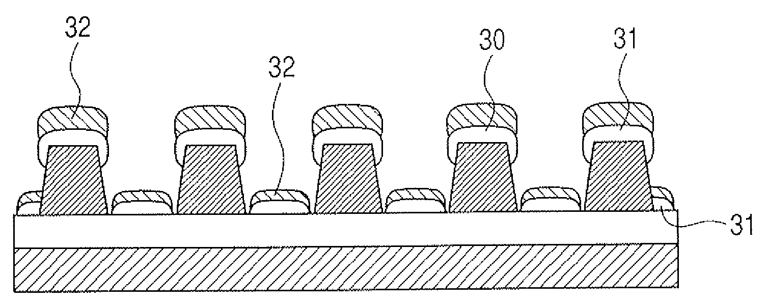
[0067]A patterned medium caused to be of the configuration including magnetic recording layers of this embodiment has features as described below.

[0068]First, plural convex members are provided in an array form on a substrate, and the convex member has shape such that the cross section at each plane in parallel to the substrate tapers toward the substrate (inverse taper shape). Further, the magnetic recording layers are provided on the upper surface parts of the convex members so that they are not in contact with each other between the adjacent upper surface parts.

[0069]Specifically, description will be given with reference to FIG. 20. In FIG. 20, reference numeral 2990 indicates substrate, reference numeral 2991 indicates convex member, and reference numeral 2992 indicates magnetic film on the member. As occasion demands, different layers for various objects may be interposed between the substrate and the convex member, or between the member and the magnetic film. Reference numeral...

examples

[0156]Examples of the present invention will now be described.

first example

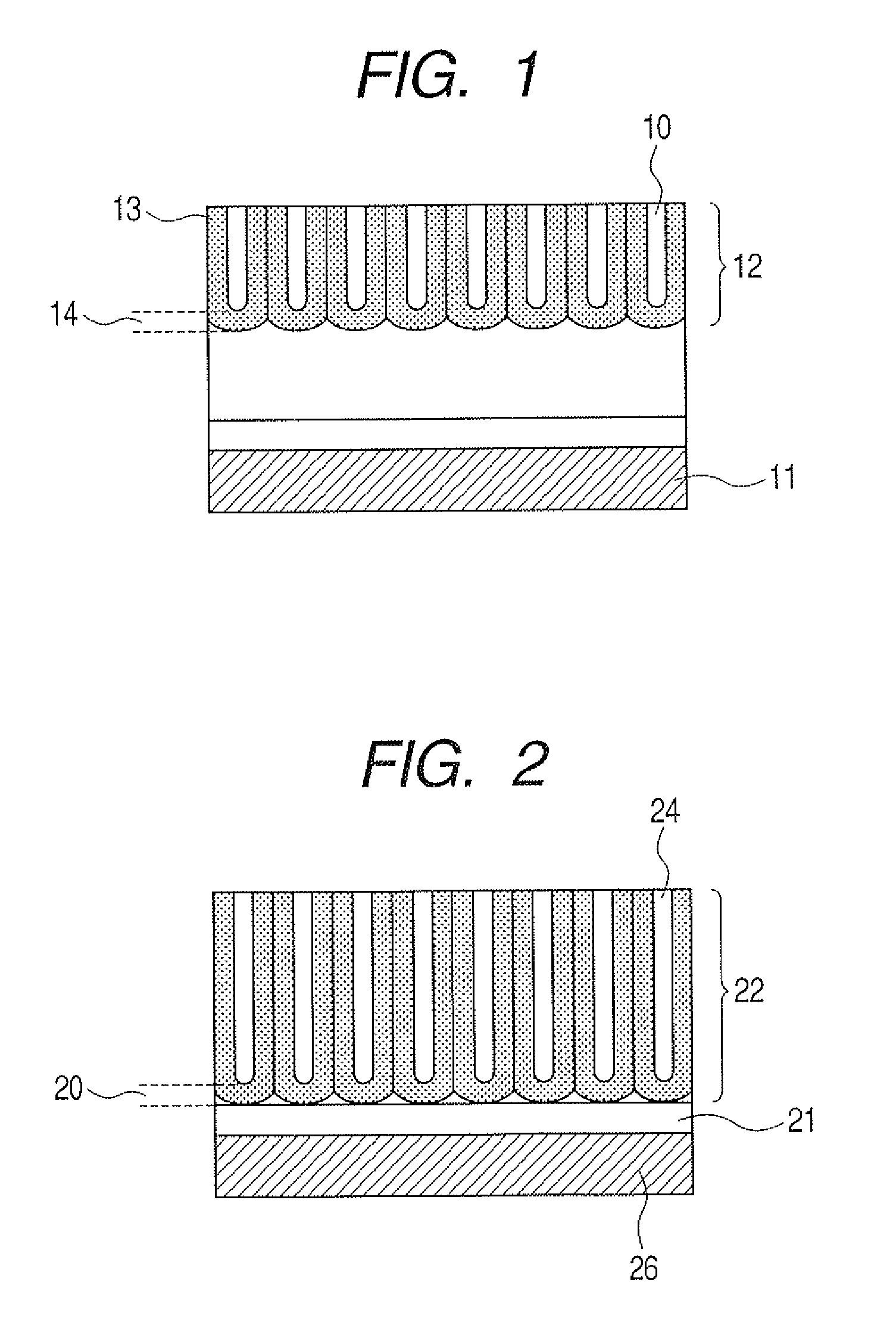
[0157]This example relates to the fact that an uneven structure including regularly arranged projections is provided by anodic oxidation to dispose a magnetic material on the upper part of the projection.

[0158]Ti serving as underlying layer was formed as film on a Si substrate so that the film thickness became equal to 5 nm by sputtering, and AlTi containing Ti 10 atomic % was further formed as film on the Ti layer by sputtering so that the film thickness was equal to 100 nm.

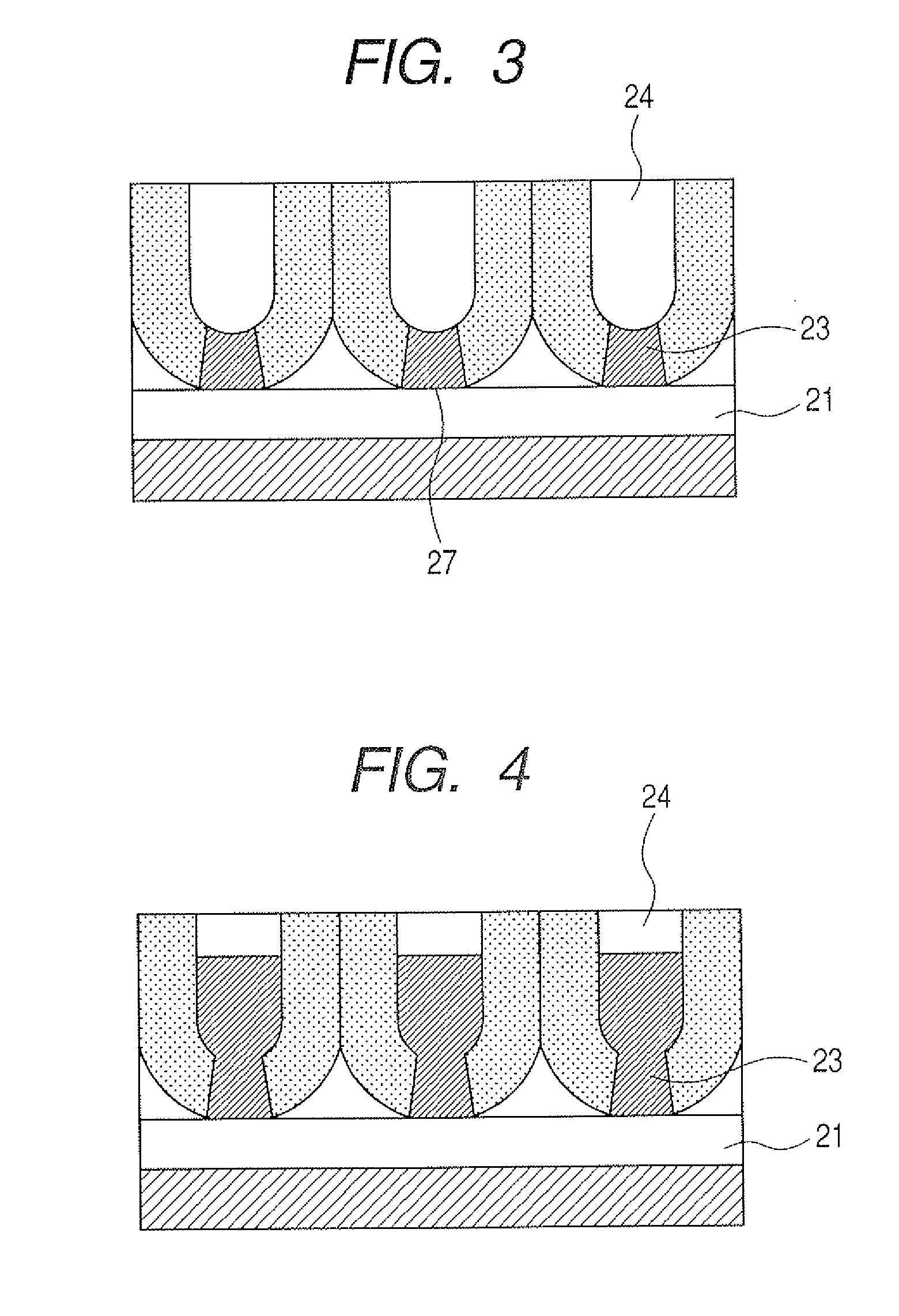
[0159]Next, aluminum alkoxide was coated on the sample surface by the spin-coat process so that its thickness became equal to 20 nm. Subsequently, the sample was baked for 20 minutes at 90° C. thereafter to transfer concave part serving as starting point of anodic oxidation onto the alkoxide surface by the nano in-print method. In this example, mold in which projections having height of 15 nm were arranged in a triangular lattice formed at intervals of 50 nm was pressed onto the alkoxide surface to thereby trans...


PUM

PropertyMeasurementUnit
heightaaaaaaaaaa
heightaaaaaaaaaa
heightsaaaaaaaaaa

Abstract

To provide patterned media having novel structure. Plural convex members 2991 are provided in an array form on a substrate 2990. The convex member has a shape such that the cross section at each plane in parallel to the substrate tapers toward the substrate. Magnetic recording layers 2992 are provided on upper parts 2993 of the convex members so that they are not in contact with each other between the adjacent upper surface parts.

Description

BACKGROUND OF THE INVENTION[0001]1. Field of the Invention[0002]The present invention relates to patterned media. Moreover, the present invention relates to a method of manufacturing a magnetic recording medium, and more particularly to a magnetic recording medium used for information recording media. Further, the present invention relates to a method of manufacturing a base.[0003]2. Description of the Related Art[0004]With recent rapid increase in information processing quantity, realization of large increase in capacity is required in magnetic recording media widely used as an information recording medium. Particularly, in hard discs, large increase in capacity and large increase in recording density have been realized until now with development of fine processing technology and signal processing technology, etc. being supported. However, nowadays, recording density is becoming close to about 200 Gbits / in2 which has been considered to be physical limit from the problem of thermal ...

Claims


Application Information

Patent Timeline
Patent Type & Authority Applications(United States)
IPC IPC(8): G11B5/82
CPCB82Y10/00G11B5/667G11B5/855G11B5/82G11B5/8404G11B5/743
Inventor SAITO, TATSUYANAKAMURA, TAKASHIICHIHARA, SHIGERUDEN, TORUIMADA, AYAYASUI, NOBUHIRO
Owner CANON KK
Why Eureka
Try Eureka