Tapered prism illumination apparatus for LCD backlight

Inactive Publication Date: 2008-02-14
TSUNG WEN CHAN
View PDF2 Cites 32 Cited by
  • Summary
  • Abstract
  • Description
  • Claims
  • Application Information

AI Technical Summary

Benefits of technology

[0013]It is a primary object of the present invention to provide a tapered prism illumination apparatus for LCD backlight that uses high power LEDs as the source of light and allows the light from the source projected onto the tapered prism to be refracted with an appropriate angle to the surroundings of a reflector and then reflected onto a guide-light plate, so that the light from the source can be reflected to the LCD for colors of high brightness and high saturation presented thereon.
[0014]It is another object of the present invention to provide a tapered prism illumination apparatus for LCD backlight that provides a specific mechanism of heat dissipation for manufacturing backlight illumination modules according to a unique specification, thereby decreasing the probability of breakdown due to heat and promoting the yield and brightness for large size LCDs.
[0015]It is a further object of the present invention to provide a tapered prism illumination apparatus for LCD backlight, wherein the LEDs consist of minimolds and, as a result, when a single device is damaged, the module thereof can be replaced directly so that maintenance of large size LCDs is simple and feasible.
[0016]A tapered prism illumination apparatus for LCD backlight capable of fulfilling the purpose described above comprises an LCD, a plurality of LEDs, and a heat dissipation base. The plurality of LEDs is mounted in the back of the LCD, for generating and projecting light onto the LCD, and consists of high power LEDs capable of generating adequate light, wherein each of the LEDs includes a light emitting point that is packaged exteriorly with a transparent covering body and, on the light emitting path of the LED, a tapered prism is disposed. In the periphery of the LED a thermally conducting substrate is disposed, while the heat dissipation base is mounted in the rear of the LEDs and has reflecting faces, which are inclined planes, in the periphery of each of the LEDs. When light is emitted from the light emitting point, it can be projected onto the tapered prism, by which it is bent by an appropriate angle, and then projected via the reflecting faces onto a guide-light plate and a diffuser so as to uniformly spread on the LCD. The heat generated by the high power LEDs is conducted by the thermally conducting substrate to the heat dissipation base and, thus, the stability of the product can be kept.

Problems solved by technology

1. The CCFL has non-uniform brightness. Even if as mamy as possible CCFLs are connected, the brightness that can be acquired within the range of LCD's size is still non-uniform, especially for large size LCDs.
2. The CCFL has a shorter life. The brightness starts to fade for a use of about 4000-6000 hours and it is not easy to make a replacement, resulting in a largely reduced lifespan.
3. The CCFL has inadequate color saturation. It has a color temperature at about 4800 K, so that only a gamut of about 80% given in the NTSC (National Television System Committee) standard can be reached and, especially for red light, the performance is even worse. Thus, it is impossible to meet the requirement for high-specification color. For example, color imperfections can be clearly found in the situation of measurement with instruments or in the environment of a specific color performance.
4. The CCFL leads to higher power consumption in use; moreover, the noxious substance “mercury” would be involved in manufacturing, certainly resulting in harm to the environment, so the Kyoto Protocol agreed on the inhibition of use on 1 Jul. 2006. Therefore, to adopt other sources of backlight becomes an inevitable tendency in the development of the LCD.
However, typically light from LEDs is not scattered uniformly, but is focused in a small range and makes a particularly bright area on the LCD that has been subjected to the light projection.
Yet, in the surroundings of the bright area notable brightness fading can be found and color can not be exhibited uniformly.
Besides, in any LCD apparatus mentioned above, overall instead of individual replacement of the illumination apparatus for backlight would be necessary when only a part thereof is damaged, thus making a very high cost.
Moreover, not only the inevitable elimination of a single device leads to a waste of resource, but also the LCD wastes would cause a burden on the environmental protection.

Method used


Image

  • Tapered prism illumination apparatus for LCD backlight
  • Tapered prism illumination apparatus for LCD backlight
  • Tapered prism illumination apparatus for LCD backlight

Examples


Embodiment Construction

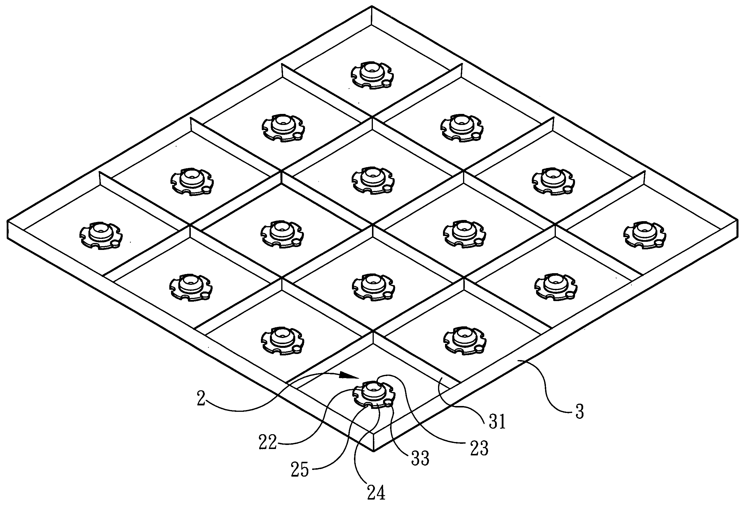
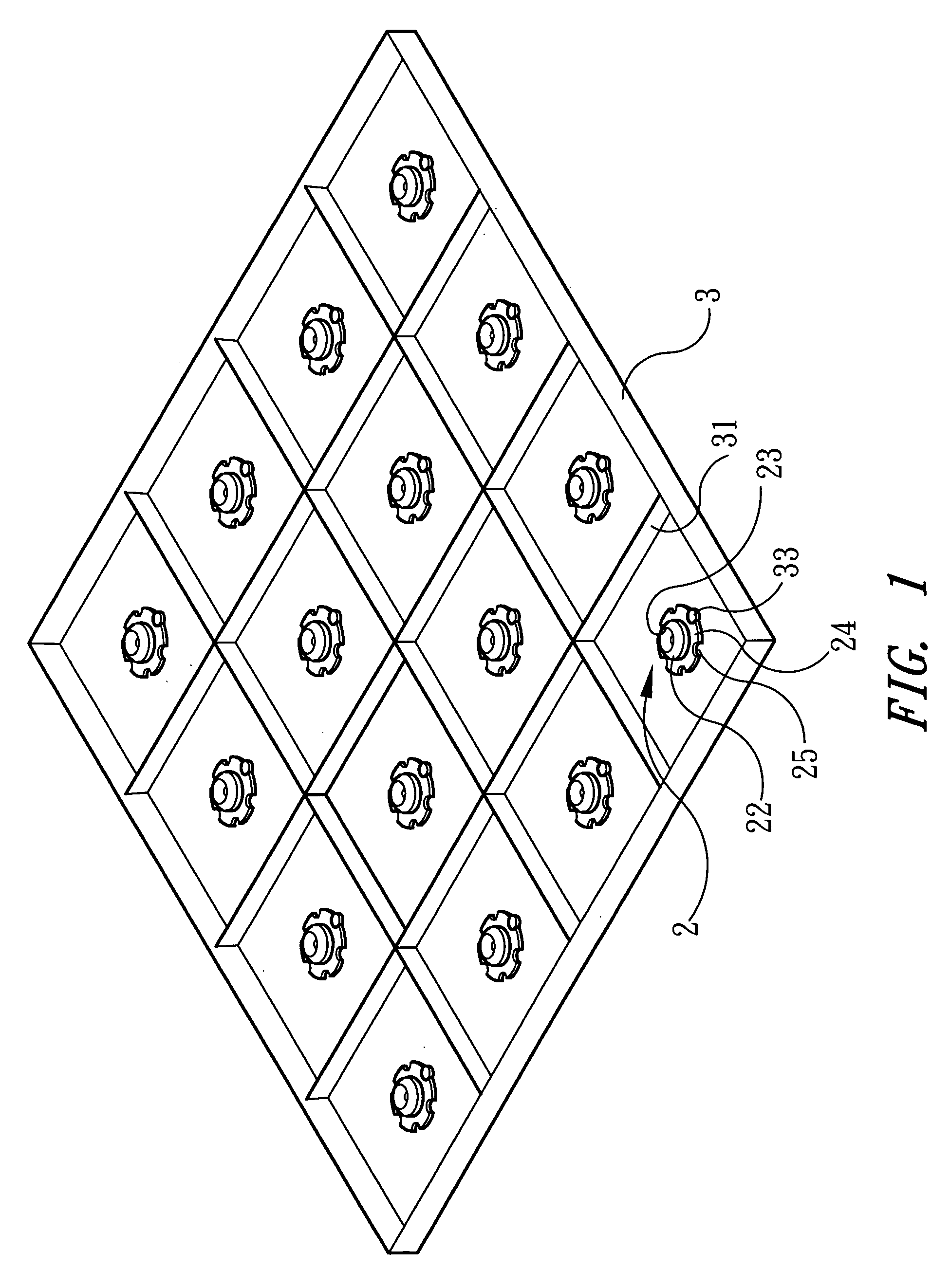
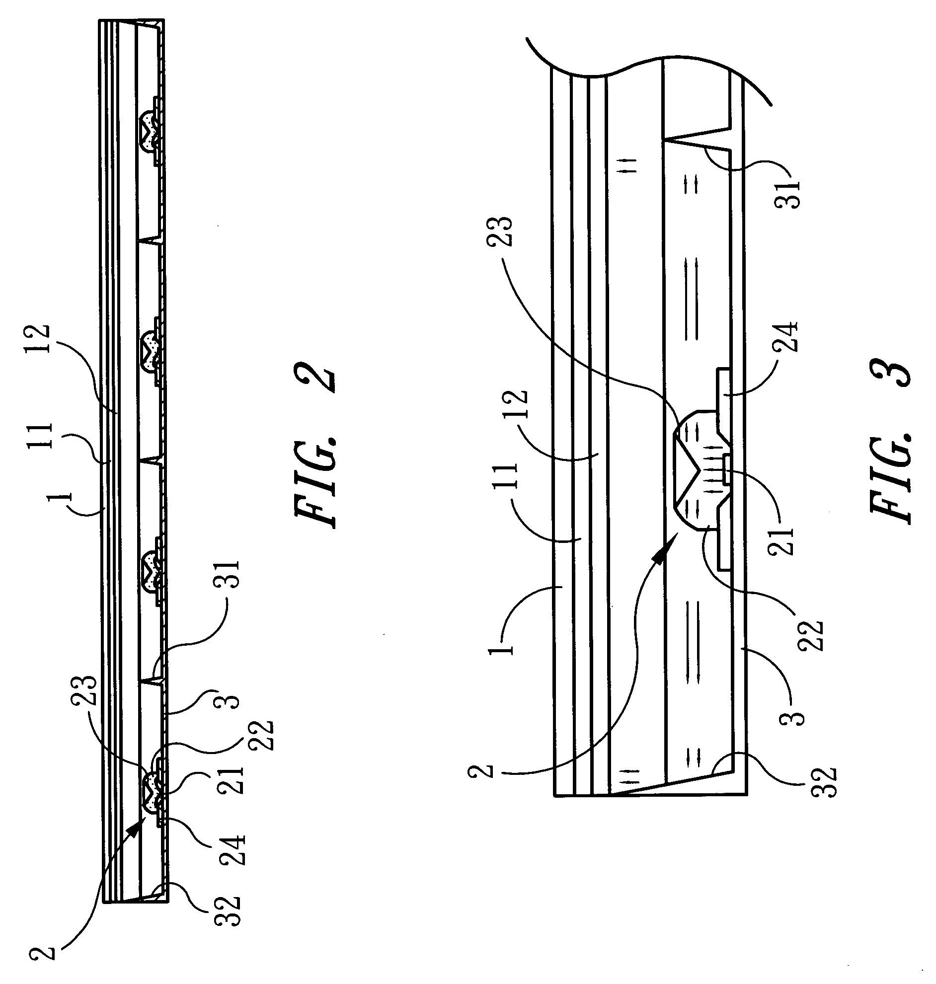
[0021]Referring to FIG. 1-3, the present invention provides a tapered prism illumination apparatus for LCD backlight, the apparatus comprising an LCD 1, a plurality of LEDs 2, and a heat dissipation base 3. The LCD 1 is used for producing an image, with a diffuser 11 and a guide-light plate 12 disposed in the back thereof, wherein the diffuser 11 is used for receiving the light from the source and performing a uniform distribution to prevent the light from focusing at one point, while the guide-light plate 12 is used for further scattering the light uniformly to make the image on the LCD 1 have even brightness and saturated color.

[0022]The plurality of LEDs 2 is mounted in the back of the LCD 1, for generating and projecting light onto the LCD 1, and consists of high power LEDs capable of generating adequate light. Each of the plurality of LEDs 2 includes a light emitting point 21 that is packaged exteriorly with a transparent covering body 22 and, on the light emitting path of the ...


PUM


Abstract

A tapered prism illumination apparatus for LCD backlight consists of an LCD, a plurality of LEDs and a heat dissipation base. The plurality of LEDs consists of high power LEDs mounted in the back of the LCD, wherein each of the LEDs includes a light emitting point that is packaged exteriorly with a transparent covering body and, on the light emitting path of the LED, a tapered prism is disposed. In the periphery of the LED a thermally conducting substrate is disposed, while the heat dissipation base is mounted in the rear of the LEDs and has reflecting faces in the periphery of each of the LEDs. When light is generated at the light emitting point, it can be projected onto the tapered prism, by which it is bent by 90°, and then projected onto the LCD via the reflecting faces. The heat generated by the high power LEDs is conducted by the thermally conducting substrate to the heat dissipation base to be removed.

Description

BACKGROUND OF THE INVENTION[0001]1. Field of the Invention[0002]The present invention relates to a tapered prism illumination apparatus for LCD backlight and, more specifically, to an illumination apparatus for LCD backlight that can be assembled in modules and manufactured and maintained easily, and can present uniform and saturated brightness and color.[0003]2. Description of Related Art[0004]Current illumination apparatuses for LCD (liquid crystal display) backlight are mainly the white-light cold cathode fluorescent lamp (CCFL), which is disposed in the back of an LCD, emitting and projecting light onto the guide-light plate, diffuser and brightness enhancement film and subsequently spotting the light onto the LCD, so that an image may be displayed on the LCD. In view of the increasingly larger size of the LCD, the required CCFL and the driving circuit thereof must have increased sizes as well. In order to attain the backlight illumination function of large size LCDs, it is nece...

Claims


Application Information

Patent Timeline
IPC IPC(8): F21V7/04
CPCG02F1/133603G02F2001/133628G02F2001/133607G02F1/133605G02F1/133607G02F1/133628
Inventor CHAN, TSUNG-WEN
Owner TSUNG WEN CHAN
Why Eureka
Try Eureka