Implant

a technology of implants and implants, applied in the field of implants, can solve problems such as fractures in bone tissue, and achieve the effect of increasing the stiffness of implants

Inactive Publication Date: 2008-02-14
ASTRA TECH SE
View PDF16 Cites 17 Cited by
  • Summary
  • Abstract
  • Description
  • Claims
  • Application Information

AI Technical Summary

Benefits of technology

[0010] The larger inter-peak spacing in the second axial section of circumferentially-oriented roughness acts to promote primary fixation of the implant in the bone tissue during the early phases of osseointegration since each trough between adjacent peaks can capture a relatively large volume of bone tissue to interlock the implant with the bone tissue. The smaller inter-peak spacing in the first axial section, on the other hand, enables the stiffness of the implant to be increased thereby improving the ability of the implant to transmit loads more evenly to the bone tissue to inhibit marginal bone resorption. Adapting the first and second axial sections to have the same or substantially the same pitch means that both axial sections produce the same or substantially the same axial displacement into the bone tissue on one rotation thereof thus ensuring that the provision of the two different axial sections of circumferentially-oriented roughness does not complicate insertion of the implant into the bone tissue. If the first and second axial sections of circumferentially-oriented roughness did not have the same or substantially the same pitch then a greater force would need to be applied to insert the implant resulting in fractures being formed in the bone tissue.
[0019] In an embodiment of the invention such as the one hereinafter to be described the height of the peaks, as measured from the troughs to the crests, in the first axial section differs from that in the second axial section. To advantage, the height of the peaks in the first axial section is less than that in the second axial section. This feature further enables the stiffness of the implant to be increased.

Problems solved by technology

If the first and second axial sections of circumferentially-oriented roughness did not have the same or substantially the same pitch then a greater force would need to be applied to insert the implant resulting in fractures being formed in the bone tissue.

Method used


Image

  • Implant
  • Implant
  • Implant

Examples


Embodiment Construction

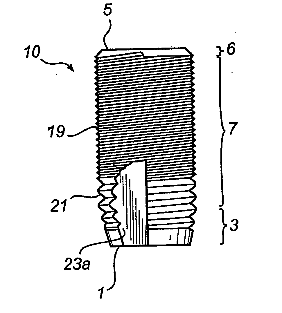
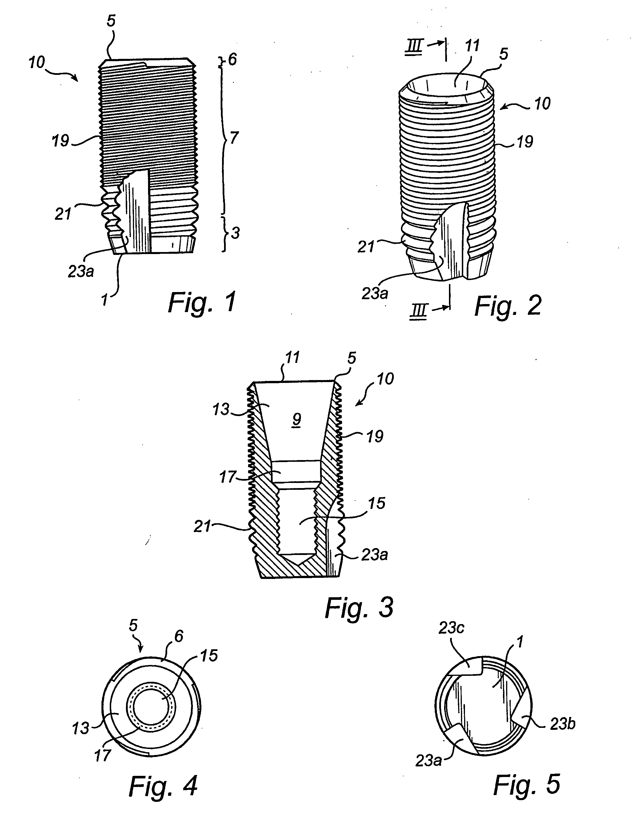
[0041] In the accompanying Figures of drawings there is shown various views of a self-tapping endosseous screw-type dental implant 10 of a dental prosthesis in accordance with the present invention. The implant 10 is for insertion into a bore-hole drilled into a toothless-site in a maxilla or mandible of a partially or fully edentulous patient to anchor to the maxilla or mandible a superstructure of the prosthesis which comprises a prosthetic part, namely one or more artificial teeth. The implant 10 is made from commercially pure titanium, a titanium alloy, another biocompatible metal or metal alloy or a ceramic to promote osseointegration of the implant with the bone tissue of the boundary walls of the bore-hole.

[0042] Referring to FIG. 1, the implant 10 has an apical end 1 which is presented by a first conical section 3 to ease insertion of the implant 10 into the bore-hole, a coronal end 5 presented by a second conical section 6 and an intermediate section 7 of constant diameter...


PUM


Abstract

Implant (10) having a shaft which is adapted in use to be embedded in bone tissue and which has an outer surface provided with a circumferentially-oriented roughness. The circumferentially-oriented roughness has first and second axial sections (19, 21) with each section comprising a series of circumferentially-oriented peaks which have a crest and which are axially spaced apart by troughs. The axial spacing (d) between the crests of adjacent peaks in the first axial section (19) is less than the axial spacing (3d) between the crests of adjacent peaks in the second axial section (21). Although the axial spacing between the crests of adjacent peaks in the first and second axial sections of circumferentially-oriented roughness differs, the first and second axial sections of circumferentially-oriented roughness are adapted in use to provide the same or substantially the same pitch.

Description

FIELD OF THE INVENTION [0001] The present invention relates to an implant having a shaft which is adapted in use to be embedded in bone tissue and which has an outer surface provided with a circumferentially-oriented roughness. This will hereinafter be referred to as an “implant of the type defined”. BACKGROUND OF THE INVENTION [0002] Implants of the type defined are known for use as the anchoring members of dental and orthopaedic prostheses. To this end, the implant is inserted into a bore-hole drilled into the bone tissue of a bone tissue structure at a site where a prosthesis is required, ordinarily by screwing of the implant into the bore-hole. The convention in the art is for the circumferentially-oriented roughness to take the form of a screw thread and in this case the bore-hole will ordinarily be (i) provided with internal threads in advance, or (ii) left un-tapped with the implant being provided with a self-tapping capacity, e.g. by the provision of one or more axially-exte...

Claims


Application Information

Patent Timeline
Patent Type & Authority Applications(United States)
IPC IPC(8): A61C17/00A61F2/02A61B17/86A61C8/00A61F2/28
CPCA61B17/863A61C8/0025A61C8/0022A61C8/00
Inventor HANSSON, STIG
Owner ASTRA TECH SE
Why Eureka
Try Eureka