Image display device

Active Publication Date: 2008-02-14
OLYMPUS CORP
View PDF3 Cites 46 Cited by
  • Summary
  • Abstract
  • Description
  • Claims
  • Application Information

AI Technical Summary

Problems solved by technology

Thus, there has been a problem that, when a slider is moved to the position of a mark attached to the time bar, it is difficult to identify which of a group of partial images displayed in the display area are bleeding images.
If a mark to indicate a bleeding image is additionally displayed near a bleeding image currently displayed in the display area, there has a possibility that observation of images inside a subject displayed in the

Method used


Image

  • Image display device
  • Image display device
  • Image display device

Examples


first embodiment

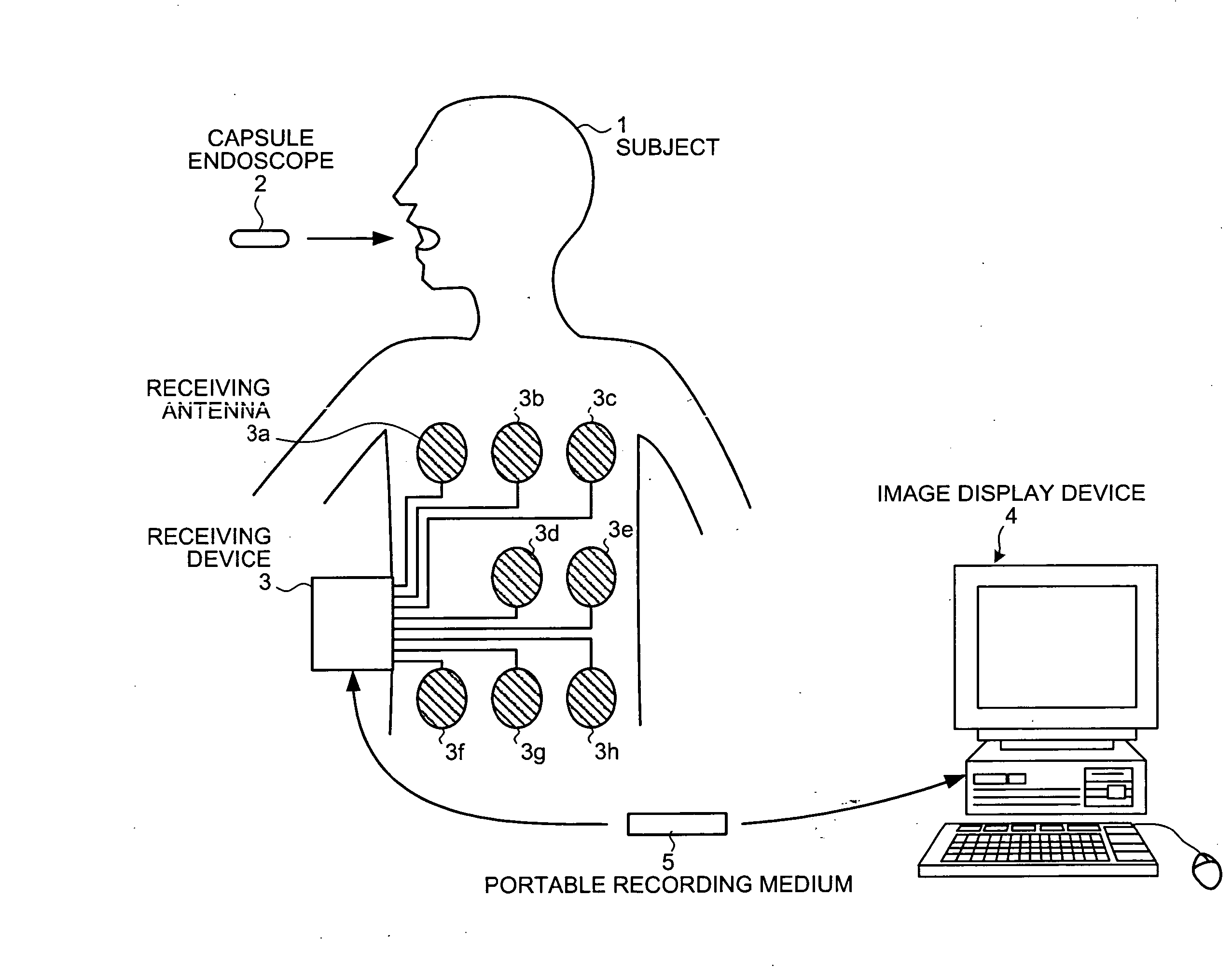
[0054]FIG. 1 is a schematic view exemplifying a configuration example of an in-vivo information acquiring system having an image display device according to a first embodiment of the present invention. As shown in FIG. 1, the in-vivo information acquiring system according to the first embodiment of the present invention comprises a capsule endoscope 2 for picking up images inside a subject 1, a receiving device 3 for receiving images inside the subject 1 picked up by the capsule endoscope 2, an image display device 4 for displaying an image inside the subject 1 received by the receiving device 3, and a portable recording medium 5 for exchanging data between the receiving device 3 and image display device 4.

[0055] The capsule endoscope 2 is used to pick up images inside a subject (more specifically, images inside organs). The capsule endoscope 2 has an imaging function, after being introduced into the subject 1, to successively pick up images inside the subject 1 in a time series an...

second embodiment

[0112] Next, a second embodiment of the present invention will be described. In the first embodiment described above, one kind of lesion images (for example, bleeding images) contained in all in vivo images AI is detected, but in the second embodiment, multiple kinds of lesion images contained in all in vivo images AI are detected and a different lesion color of the slider 111 is used for each lesion indicated by multiple kinds of lesion images. Bleeding images in which a bleeding site inside the subject 1 is picked up and fading images in which a fading site inside the subject 1 is picked up are exemplified below as multiple kinds of lesion images contained in all in vivo images AI.

[0113]FIG. 7 is a block diagram schematically showing a configuration example of an image display device according to the second embodiment of the present invention. As shown in FIG. 7, an image display device 24 according to the second embodiment has a control unit 25, instead of the control unit 15 of...

third embodiment

[0162] Next, a third embodiment of the present invention will be described. In the aforementioned second embodiment, multiple kinds of lesion images contained in all in vivo images AI are detected and the slider 111 is displayed in the lesion color that is different for each lesion indicated by each of the multiple kinds of lesion images, but in the third embodiment, an image display device is configured in such ways that desired lesions can further be selected from the multiple kinds of lesions indicated by the multiple kinds of lesion images to display the lesion colors of the lesion marks and the slider 111 corresponding to the selected desired lesions.

[0163]FIG. 12 is a block diagram schematically showing a configuration example of an image display device according to the third embodiment of the present invention. As shown in FIG. 12, an image display device 34 according to the third embodiment has a control unit 35 instead of the control unit 25 of the image display device 24 ...


PUM


Abstract

A device for displaying in vivo images picked up inside a subject in a time series. The device automatically detects lesion images contained in all in vivo images picked up over the time series. The device displays an elongated display area having a time scale assigned along a longitudinal direction thereof and an indicator which moves along the time scale to indicate a time position in the time scale which corresponds to a current in vivo image currently displayed in a main display area. In response to a detection of the lesion image, the device makes pixels located at a time position in the elongated display area which position corresponds to the lesion image to emit light in a predetermined pixel-display mode. The display mode of the indicator is controlled in response to information on a lesion that is possible to be contained in the current in vivo image.

Description

CROSS-REFERENCE TO RELATED APPLICATIONS [0001] This application is based upon and claims the benefit of priority from Japanese Patent Application No. 2006-212510, filed Aug. 3, 2006; and Japanese Patent Application No. 2006-240384, filed Sep. 5, 2006, the entire contents of both of which are incorporated herein by reference. BACKGROUND OF THE INVENTION [0002] 1. Field of the Invention [0003] The present invention relates to an image display device that displays each image contained in a group of images picked up in a time series inside a subject or a patient's body. [0004] 2. Description of the Related Art [0005] In the field of endoscope, capsule endoscopes of swallow-type equipped with an imaging function and radio communication function have been proposed and in-vivo information acquiring systems for acquiring a group of images inside organs by inserting such a capsule endoscope into the organs of a subject have been developed. A capsule endoscope is swallowed through the month o...

Claims


Application Information

Patent Timeline
IPC IPC(8): A61B1/04
CPCA61B1/00045A61B1/041A61B1/04
Inventor HIRAKAWA, KATSUMI
Owner OLYMPUS CORP
Why Eureka
Try Eureka