Methods and apparatuses for calibrating sensors

a technology of sensors and apparatuses, applied in the field of data processing systems, can solve the problems of affecting the performance of computer systems, affecting the accuracy of prediction, and tightening the power budget of computer systems, etc., and achieve the effect of accurate prediction

Inactive Publication Date: 2008-02-14
APPLE INC
View PDF2 Cites 27 Cited by
  • Summary
  • Abstract
  • Description
  • Claims
  • Application Information

AI Technical Summary

Benefits of technology

[0009]In one embodiment, a time-varying input current signal through a sensor coupled to a first load is provided using an auxiliary circuit that includes a switch and a fixed second load. A time-varying output voltage signal caused by the input current is measured across the sensor and sampled. Samples are stored in a memory as a vector of voltage values. A distribution of the samples having at least two distribution components is defined. Next, estimated parameters for each of the distribution components are calculated using a statistical iterative algorithm by maximizing the probability that an estimated parameter explains an actual observed distribution of the samples. The statistical iterative algorithm is performed until the estimated parameters sufficiently converge. The estimated parameters are a mean value, a variance of each of the distribution components, and the probability that a sample voltage comes from one of the distribution components. The estimated parameters are used to determine a transfer function of the sensor. The actual input current flowing through the first load is accurately predicted based on the transfer function.
[0010]A system to monitor the power may include one or more imprecise electrical sensors coupled to a first load. An electronic load is coupled to the one or more sensors to induce a predetermined change in the input current. In one embodiment, the electronic load is an auxiliary circuit having a switch and a fixed second load. A power monitor is coupled to the one or more sensors and to the electronic load. The power monitor changes an input current through the one or more sensors by a predetermined amount using the electronic load. Next, the power monitor observes and measures a difference in an output signal from the one or more sensors caused by changing of the input current. In one embodiment, the system further includes a sampler coupled to the one or more sensors that samples the output signal. The power monitor receives samples of the output signal, stores the samples in the memory, determines a distribution of samples of the output signal, and calculates estimated parameters of the distribution that is most likely to explain actual data. Further, the power monitor determines a transfer function of the one or more sensors based on the difference in the output signal. Next, the power monitor accurately predicts the actual input current flowing through the load coupled to the one or more sensors based on the transfer function.

Problems solved by technology

As the power or energy consumption of components of the computer systems continuously increases, the power budgets of the computer systems become tighter.
For example, portable computer systems, such as laptop computers, have a limited battery output capability, e.g., charge capacity.
Thus, sensor 102 is not only intrusive to computer system 100, but also may disrupt the performance of computer system 100.
On the other hand, voltmeters that are capable of reading the small voltages and Hall-effect devices are expensive.
Thus, the presence of sensor 102 negatively affects the performance and efficiency of the computer system 100 while increasing cost and board area.

Method used


Image

  • Methods and apparatuses for calibrating sensors
  • Methods and apparatuses for calibrating sensors
  • Methods and apparatuses for calibrating sensors

Examples


Embodiment Construction

[0031]The subject invention is described with reference to numerous details set forth below, and the accompanying drawings illustrate the invention. The following description and drawings are illustrative of the invention and are not to be construed as limiting the invention. Numerous specific details are described to provide a thorough understanding of the present invention. However, in certain instances, well-known or conventional details are not described in order to not unnecessarily obscure the present invention in detail.

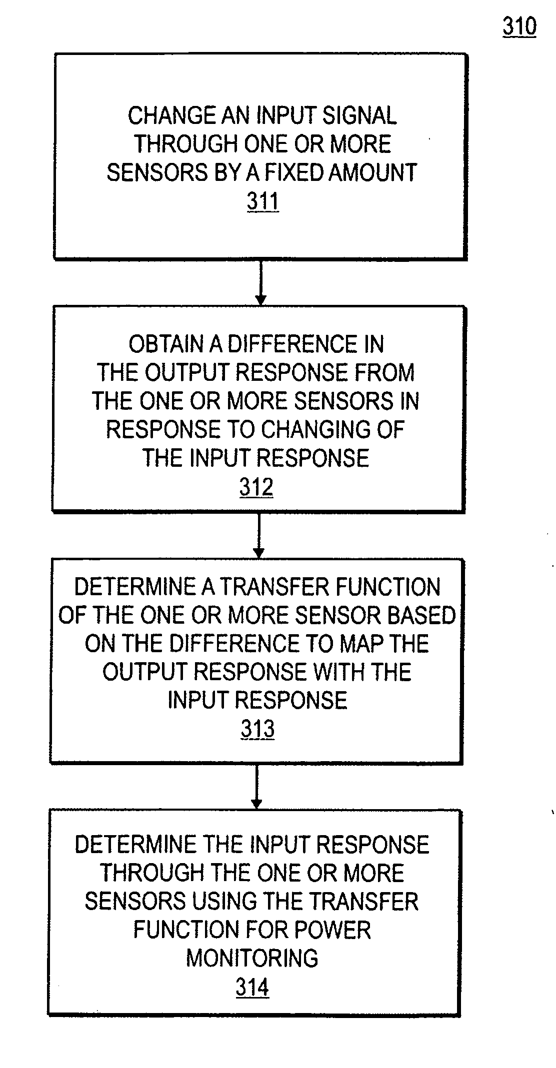
[0032]Exemplary embodiments of methods and apparatuses to perform in-circuit calibration of imprecise electrical sensing elements (“sensors”) for accurate power monitoring in a data-processing system are described below. In one embodiment, power is monitored by monitoring a current in the data-processing system, as described in further detail below. The data-processing system includes a load coupled to one or more sensors. An electronic load changes an input s...


PUM


Abstract

Methods and apparatuses to perform calibration of imprecise sensors for power monitoring in a data-processing system are described. The system includes a load coupled to one or more sensors. An electronic load changes a first input signal through one or more sensors by a predetermined amount. A difference in an output signal from the one or more sensors in response to the changing is obtained. The output signal is measured and sampled. A distribution of samples of the output signal is determined. The estimated parameters of the distribution that most likely to explain actual data are determined. Next, a transfer function of the one or more sensors is determined based on the estimated parameters. The input signal through the load is accurately predicted using the transfer function of the one or more sensors to monitor the power usage by the load.

Description

FIELD[0001]Embodiments of the present invention relate to data-processing systems, and more particularly, but not exclusively, to the management of power or energy usage in the data-processing systems.BACKGROUND[0002]As the power or energy consumption of components of the computer systems continuously increases, the power budgets of the computer systems become tighter. It is necessary to manage power or energy consumption of a computer system to pursue high-performance goals, such as high computing power, compactness, quietness, better battery performance, etc. For example, portable computer systems, such as laptop computers, have a limited battery output capability, e.g., charge capacity. Managing of the power consumption for a given battery output capability may increase the performance of the computer system and extend a battery life. Generally, the power management allows a computer system to monitor its own energy dissipation, and adjust its performance to satisfy, for example,...

Claims


Application Information

Patent Timeline
Patent Type & Authority Applications(United States)
IPC IPC(8): G06F19/00G06F17/40
CPCG06F11/24G06F1/28G01R1/203G01R27/14G01R19/0092
Inventor DORSEY, JOHN GREGORYOVERBECK, CHARLES RANDOLPHATHAS, WILLIAM C.
Owner APPLE INC
Why Eureka
Try Eureka