Round Baler

a baler and round bale technology, applied in baling, agriculture tools and machines, agriculture, etc., can solve the problems of slowed down and danger of round bale contact, and achieve the effect of preventing damage to the unloading apparatus through contact with the ground

Inactive Publication Date: 2008-02-21
DEERE & CO
View PDF30 Cites 15 Cited by
  • Summary
  • Abstract
  • Description
  • Claims
  • Application Information

AI Technical Summary

Benefits of technology

[0015]On the one hand, the unloading apparatus having the carrying element(s) could be configured as an independent and complete unit, which is merely attached to the superstructure of the round baler, on the other hand, the carrying element of the unloading apparatus could also be wrapped around a roller situated on the superstructure or the bale chamber. A gap between the cover and the carrying elements. In which crop could gather, is thereby prevented. This has the effect, furthermore, that as the round bale is ejected, the carryig element is driven, i.e. moved, which transmits itself, in turn, to the round bale. Although such a drive mechanism is known from U.S. Pat. No. 3,974,632, in this case no round bale, but rather a stack of harvested crop, is discharged from a chamber.
[0016]In order to prevent damage to the unloading apparatus through contact with the ground, a stop is provided, so that the free end of its frame always keeps a distance to the ground.
[0017]The use of a, in particular, resilient bumper at the delivery end of the frame enables the round bale to be prevented from rolling back in the direction of the bale chamber. The resilience makes it possible to roll the round bale gradually onto the ground from the ends of the frame which are distanced from the ground, instead of letting it fall. As soon as the round bale is deposited, the bumper(s) spring(s) upwards and come(s) to bear against the periphery of the round bale.

Problems solved by technology

Since the side parts of the round baler are constantly connected by relatively large transverse-running stays, of which, according to function, the axle for the running wheels also forms part, there is always the danger there that the round bale makes contact and is slowed.

Method used


Image

  • Round Baler
  • Round Baler
  • Round Baler

Examples


Embodiment Construction

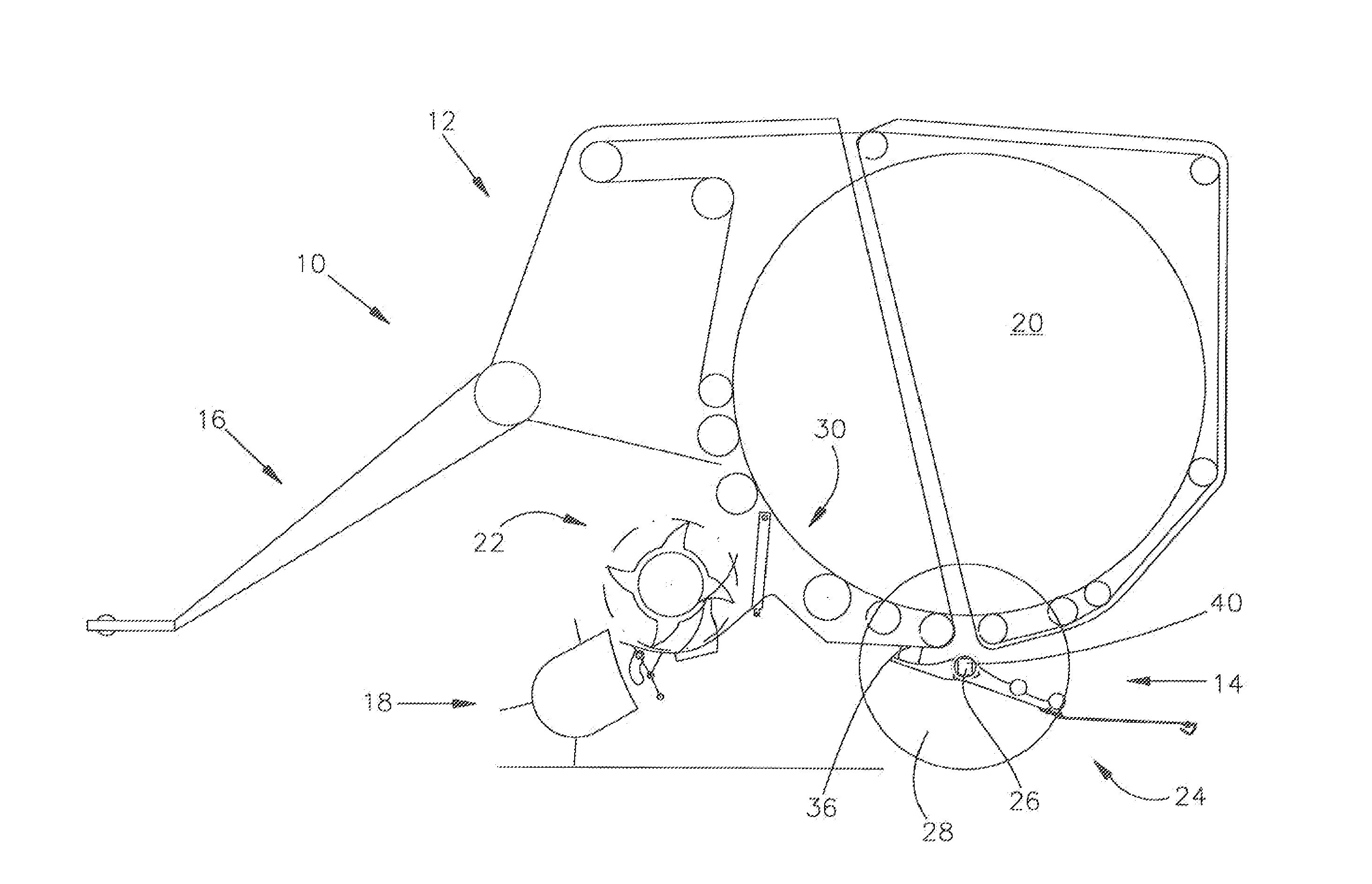
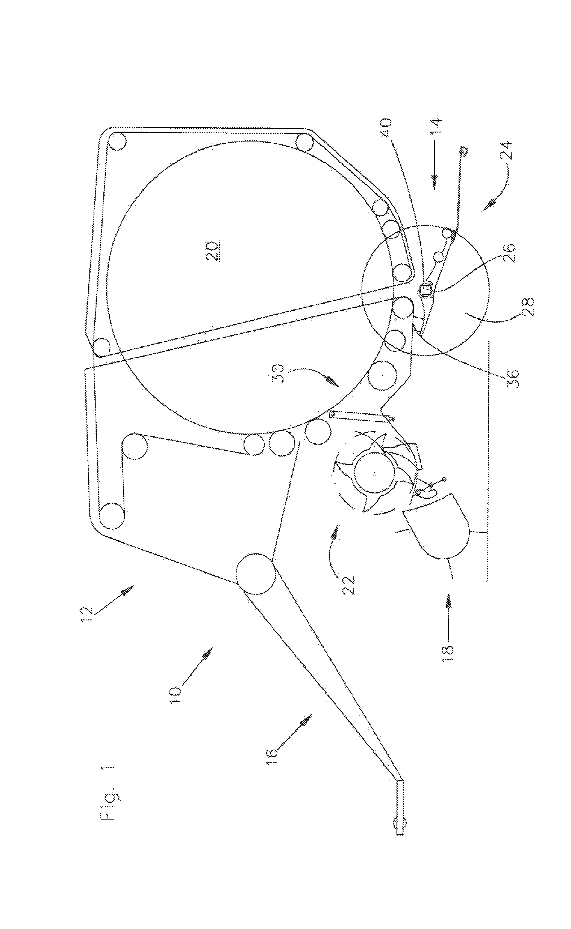
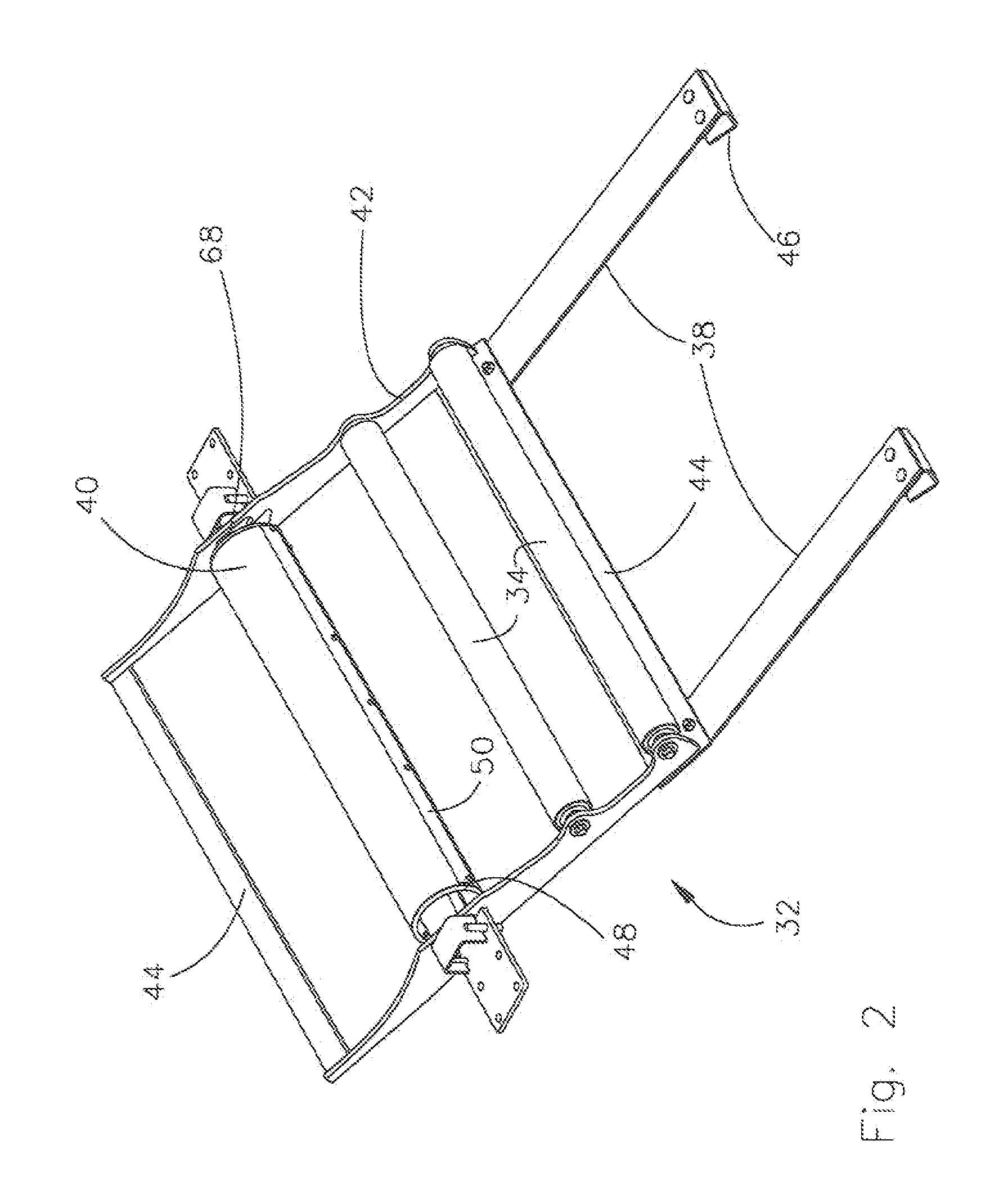
[0025]A round baler 10 shown in FIG. 1 is of standard construction, i.e. it has a superstructure 12, a chassis 14, a drawbar 16, a crop receiver 18, a bale chamber 20 and a feed apparatus 22. In addition, an unloading apparatus 24 and a cover 40 are provided, which differ, however, from the prior art or are unknown there.

[0026]The round baler 10 is represented as a drawn round baler 10 having a size-variable bale chamber 20; it could equally well be a self-propelling round baler 10 and / or one having a constant-size bale chamber 20, the type of (non-detailed) press elements being immaterial.

[0027]The superstructure 12 rests on the chassis 14 and bears the crop receiver 18, the feed apparatus 22 and the unloading apparatus 24 and forms the bale of chamber 20 between (non-detailed) single-part of multipart side walls.

[0028]the chassis 14 contains a rigidly or resiliently fitted cross-stay 26, which at the same time serves as an axle for wheels 28.

[0029]The drawbar 16 is connected in a ...


PUM


Abstract

A round baler has an unloading apparatus downstream of a bale chamber provided with movable carrying elements, for example rollers, belts, etc., so that a round bale discharged in rotating motion from the bale chamber is able to maintain its spin and twine wound onto it does not fall off again. To prevent the rotary motion of the round bale from being slowed or even terminated upon transfer to the unloading apparatus, stationary portions of a superstructure of the round baler, for example, a cross-stay serving as an axle, are covered by a movable cover.

Description

FIELD OF THE INVENTION[0001]The invention relates to a round baler comprising a superstructure, a bale chamber and a thereto adjoining unloading apparatus having at least one carrying element between the bale chamber and a ground surface, which carrying element permits a rolling motion of the round bale.BACKGROUND OF THE INVENTION[0002]Whenever a round bale is unloaded from the bale chamber of a round baler, the problem of controlling its motion always presents itself. If the round bale falls to roll far enough away from the round baler, the discharge gate cannot be lowered and the bale chamber cannot be closed. If the round bale has too much momentum, it rolls uncontrollably onwards and down a slope, for example, it is slowed too much upon discharge from the bale chamber, it remains stuck on an axle or other cross-stays and does not roll down the ramp, or its direction of rotation reverses and twine which is wound thereon falls off from the down-rolling round bale.[0003]U.S. Pat. N...

Claims


Application Information

Patent Timeline
Patent Type & Authority Applications(United States)
IPC IPC(8): A01F15/07
CPCA01F15/0883
Inventor VIAUD, JEAN
Owner DEERE & CO
Why Eureka
Try Eureka