
High performance data cable

Inactive Publication Date: 2008-02-21
BELDEN INC
View PDF99 Cites 26 Cited by
  • Summary
  • Abstract
  • Description
  • Claims
  • Application Information

AI Technical Summary

Benefits of technology

[0028] Accordingly, the present invention desires to provide a data cable that meets the exacting specifications of high performance data cables, has a superior resistance to deformation during manufacturing and use, allows for control of near-end cross talk, controls electrical instability due to shielding, and can be a 300 MHz cable with a positive ACR ratio.
[0029] It is still another desire of the invention to provide a cable that does not require individual shielding, and that allows for the precise spacing of conductors such as twisted pairs with relative ease.
[0030] It is still a further desire of the invention to provide a data cable that has an interior support that accommodates a variety of AWG's and impedances, improves crush resistance, controls NEXT, controls electrical instability due to shielding, increases breaking strength, and allows the conductors such as twisted pairs to be spaced in a manner to achieve positive ACR ratios.

Problems solved by technology

Data cables have also used very complex lay techniques to cancel E and B fields to control NEXT.
The use of the above techniques to control electrical characteristics has problems.
Individual shielding is costly and complex to process.
Individual shielding is highly susceptible to geometric instability during processing and use.
In addition, the ground plane of individual shields, 360.degree. in ISTP's, lessens electrical stability.
Lay techniques are also complex, costly and susceptible to instability during processing and use.
Another problem with many data cables is their susceptibility to deformation during manufacture and use.
Deformation of the cable's geometry, such as the shield, lessens electrical stability.

Method used


Image

  • High performance data cable
  • High performance data cable
  • High performance data cable

Examples


Embodiment Construction

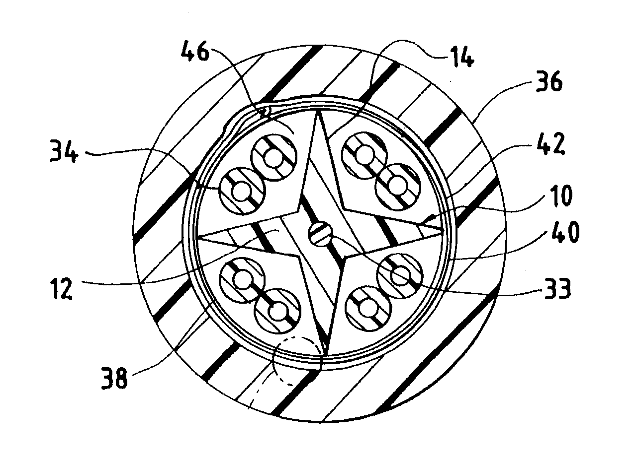
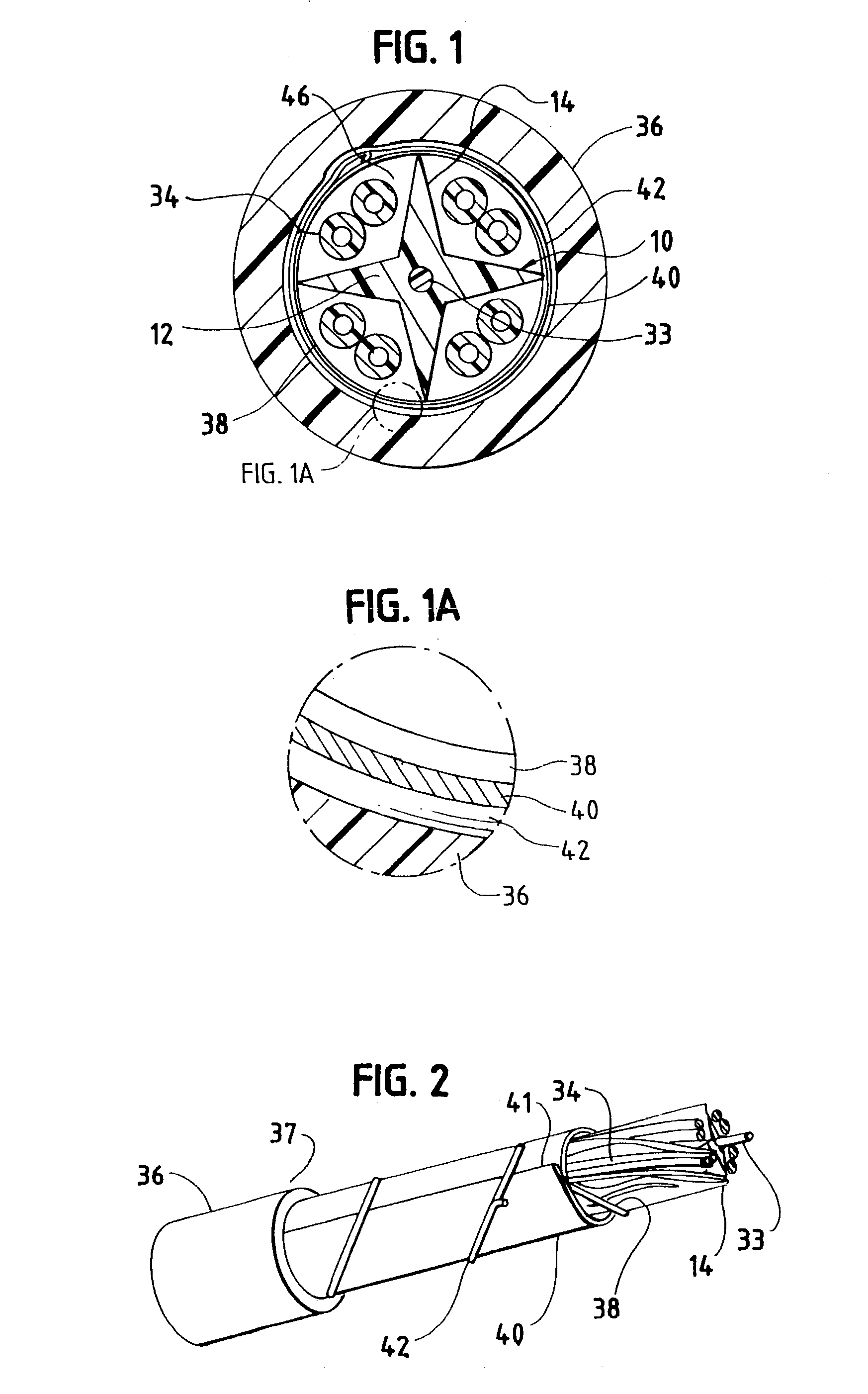
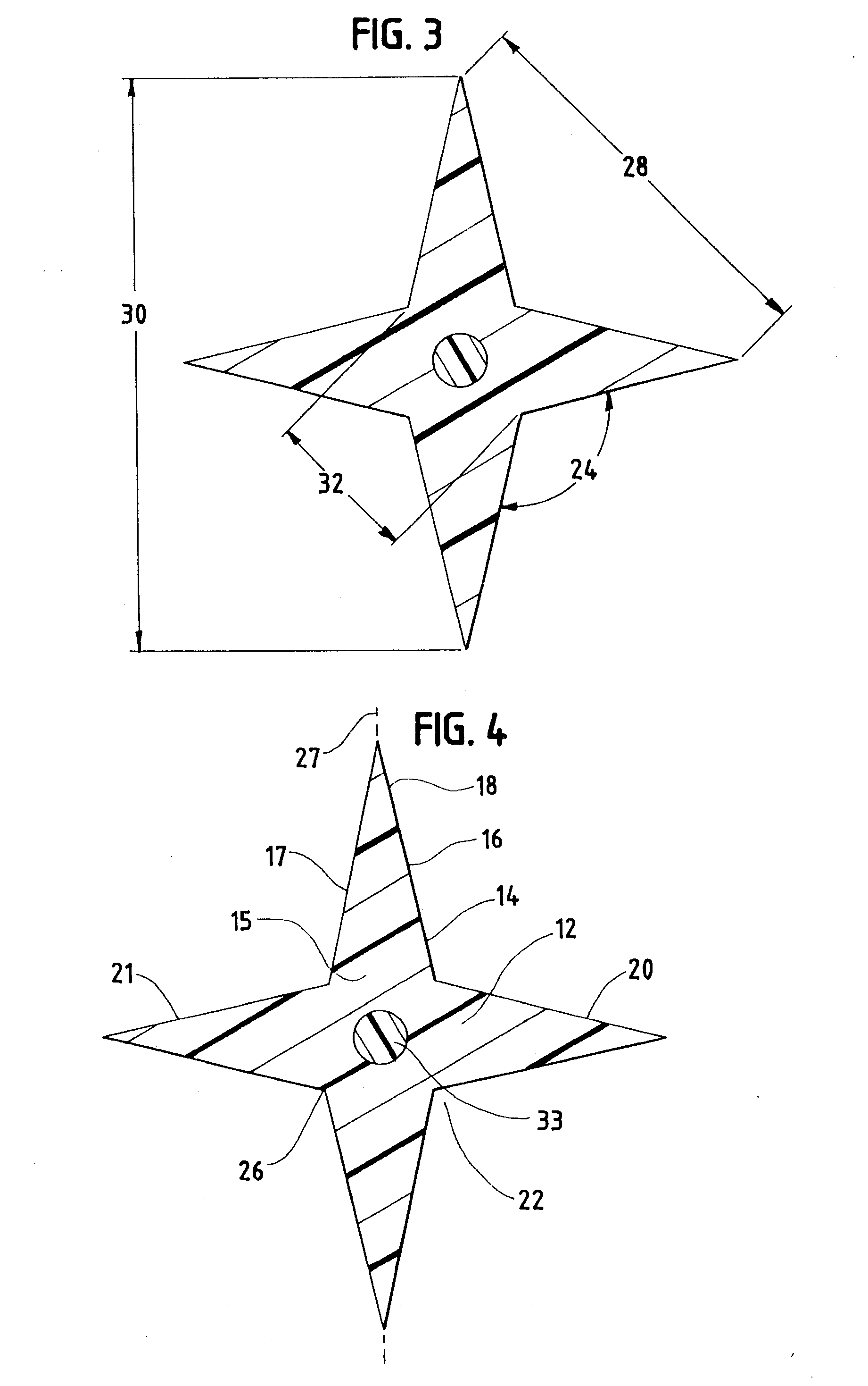
[0038] The following description will further help to explain the inventive features of this cable.

[0039]FIG. 1 is a vertical cross-section of one embodiment of this novel cable. The shown embodiment has an interior support or star separator (10). The interior support or star separator runs along the longitudinal length of the cable as can be seen in FIG. 2. The interior support or star separator, hereinafter, in the detailed description, both referred to as the “star separator”, has a central region (12) extending along the longitudinal length of the star separator. The star separator has four prongs or splines. Each prong or spline (14), hereinafter in the detailed description both referred to as splines, extends outward from the central region and extends along the longitudinal length of the central region. The splines are integral with the central region. Each spline has a base portion (15). Each base portion is integral with the central region. Each spline has a base portion w...


PUM


Abstract

The present invention is for a high performance data cable which has an interior support or star separator. The star separator or interior support extends along the longitudinal length of the data cable. The star separator or interior support has a central region. A plurality of prongs or splines extend outward from the central region along the length of the central region. Each prong or spline is adjacent with at least two other prongs or splines. The prongs or splines may be helixed or S-Z shaped as they extend along the length of the star separator or interior support. Each pair of adjacent prongs or splines defines grooves which extend along the longitudinal length of the interior support. At least two of the grooves have disposed therein an insulated conductor. The star separator in particular improves control of near end cross-talk and allows for the achievement of positive ACR ratios when twisted pair conductors are disposed in the grooves. The interior support can have a first material and a different second material. The different second material forms an outer surface of the interior support.

Description

[0001] The present application is a continuation of application Ser. No. 09 / 765,914 filed Jan. 18, 2001 which is a continuation in-part of application of application Ser. No. 08 / 629,509 filed Apr. 9, 1996 now U.S. Pat. Nos. 5,789,711 and 09 / 074,272 filed May 7, 1998 now U.S. Pat. No. 6,222,130.FIELD OF INVENTION [0002] This invention relates to a high performance data cable utilizing twisted pairs. The data cable has an interior support or star separator around which the twisted pairs are disposed. BACKGROUND OF THE INVENTION [0003] Many data communication systems utilize high performance data cables having at least four twisted pairs. Typically, two of the twisted pairs transmit data and two of the pairs receive data. A twisted pair is a pair of conductors twisted about each other. A transmitting twisted pair and a receiving twisted pair often form a subgroup in a cable having four twisted pairs. [0004] A high performance data cable utilizing twisted pair technology must meet exact...

Claims


Application Information

Patent Timeline
IPC IPC(8): H01B11/02H01B7/18
CPCH01B11/06H01B11/02
Inventor GAREIS, GALENVANDERLAAN, PAUL
Owner BELDEN INC
Learn More