Welding method for fluorine-passivated memberfor welding, fluorine-passivated method after being weld, and welded parts priority data

Inactive Publication Date: 2005-01-20
FOUND FOR ADVANCEMENT OF INT SCI +1
View PDF23 Cites 0 Cited by
  • Summary
  • Abstract
  • Description
  • Claims
  • Application Information

AI Technical Summary

Benefits of technology

[0011] The present invention has as an object thereof to provide a welding method for members to be welded which are subjected to fluoride passivation treatment, and a fluoride passivation retreatment method, which involve no generation of particles or dust, and which provide superior resistance with respect to fluorine system gases, when fluoride passivation retreatment is conducted after welding.

Problems solved by technology

When members to be welded (for example, piping, valves, and the like) which are subjected to fluoride passivation treatment are welded together to produce a fluorine gas supply line, it has been discovered that the gas which is supplied from this fluorine gas supply line becomes contaminated with particles and dust (FIG. 3).
However, when welding has been conducted, even if a fluoride passivated film is again formed, the gas which is supplied from the fluorine gas supply line constructed using such welded members is contaminated by particles and dust.
Furthermore, it is not always the case that the decline in durability with respect to fluorine system gases can be overcome.

Method used


Image

  • Welding method for fluorine-passivated memberfor welding, fluorine-passivated method after being weld, and welded parts priority data
  • Welding method for fluorine-passivated memberfor welding, fluorine-passivated method after being weld, and welded parts priority data
  • Welding method for fluorine-passivated memberfor welding, fluorine-passivated method after being weld, and welded parts priority data

Examples


embodiment 1

[0055] (Embodiment 1)

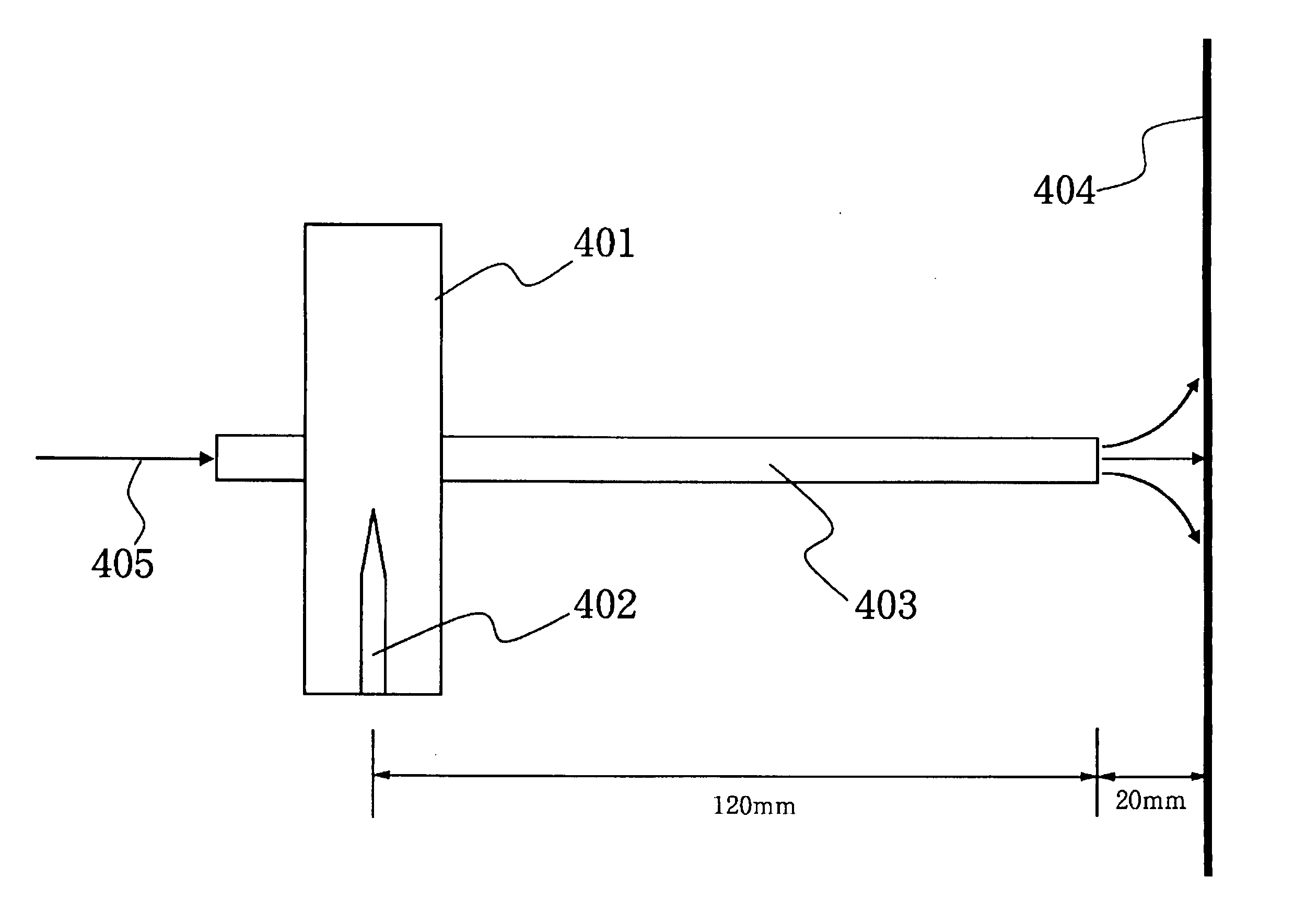
[0056] An austenitic stainless steel tube having a length of 12 cm and a diameter of {fraction (1 / 4)} inch was prepared.

[0057] The inner surface of this tube was subjected to electropolishing, and the surface roughness thereof was set to an Rmax of 0.7 micrometers. After electropolishing, this was maintained for a period of 10 hours at a temperature of 250° C. in an atmosphere of 100% nitrogen gas having a moisture concentration of 10 ppb or less.

[0058] Next, this was maintained at a temperature of 150° C. for a period of 3 hours in an atmosphere of 1% fluorine gas in nitrogen gas to produce a fluoride passivated film.

[0059] Subsequently, treatment was conducted for a period of 10 hours at 200° C. in a 100% nitrogen gas atmosphere having a moisture concentration of 10 ppb or less.

[0060] As a result of the treatment described above, a fluoride passivated film having a thickness of approximately 20 nm was formed on the inner surface.

[0061] This piping was sub...

embodiment 2

[0069] (Embodiment 2)

[0070] Experimentation identical to that of embodiment 1 was conducted, and the results obtained when the flow rate of the back shield gas was altered (the hydrogen concentration was 5%) are shown in Table 2.

TABLE 2StandardWeldingAmountFlowofBack Shield Gas Flow rateRateMetal1 L / min3 L / min6 L / min10 L / min20 L / min6 L / minFe3.73.620.424.222.315.4Cr5.64.15.88.911.521.1Ni0.30.30.10.40.40.6Mn0.30.41.01.41.32.4

(The units are × 1010 atom / cm2)

[0071] From Table 2, it can be seen that when the flow rate is increased, the amount of metal deposited on the silicon wafer is increased, and the contamination of the inner surface of the pipe is prevented. There is almost no change when the flow rate is increased to a level of greater than 10 L / min, and it is thus presumed that the optimal flow rate for the back shield gas is within a range of 6 L / min-10 L / min.

embodiment 3

[0072] (Embodiment 3)

[0073] An austenitic stainless steel tube having a diameter of ¼ inch was prepared, and this was subjected to fluoride passivation treatment to a thickness of approximately 200 nm.

[0074] The formation of the fluoride passivated film was conducted in the following manner.

[0075] The inner surface of the tube was subjected to electropolishing, and the surface roughness was set to an Rmax of 0.7 micrometers. After electropolishing, this was maintained for a period of 10 hours at a temperature of 350° C. in a 100% nitrogen gas atmosphere with a moisture concentration of 10 ppb or less.

[0076] Next, this was maintained for a period of 80 minutes at 220° C. in a 100% fluorine gas atmosphere to produce a fluoride passivated film.

[0077] After this, the tube was subjected to treatment for a period of 10 hours at a temperature of 300° C. in a 100% nitrogen gas atmosphere with a moisture concentration of 10 ppb or less.

[0078] Such tubes were immersed in the variety of c...


PUM

PropertyMeasurementUnit
Temperatureaaaaaaaaaa
Lengthaaaaaaaaaa

Abstract

The present invention provides a welding method for materials to be welded which are subjected to fluoride passivation treatment, and a fluoride passivation retreatment method, wherein, when fluoride passivation retreatment was conducted after welding, there is no generation of particles or dust, and superior resistance is provided to fluorine system gases. In the present invention, when materials to be welded comprising stainless steel subjected to fluoride passivation treatment are welded, hydrogen is added to the gas (the back shield gas) flowing through the materials to be welded. Furthermore, in the welding method for materials to be welded which are subjected to fluoride passivation treatment in accordance with the present invention, the thickness of the fluoride passivated film in a predetermined range from the butt end surfaces of the materials to be welded, comprising stainless steel subjected to a fluoride passivation treatment, is set to 10 nm or less, and welding is conducted. Furthermore, in the fluoride passivation retreatment method in accordance with the present invention, after conducting the welding method described above, at least the welded parts are heated, and a gas containing fluorine gas is caused to flow in the interior part.

Description

CROSS-REFERENCE TO RELATED APPLICATIONS [0001] This case is a divisional of co-pending U.S. patent application Ser. No. 09 / 748,883.BACKGROUND OF THE INVENTION AND DESCRIPTION OF RELATED ART [0002] 1. Technical Field [0003] The present invention relates to a welding method for welded members subjected to fluoride passivation treatment, to a fluoride passivation retreatment method, and to welded products. [0004] 2. Background Art [0005] In, for example, semiconductor manufacturing lines, because a fluorine system gas is supplied in a stable manner over a long period of time in a fluorine system gas supply line (chiefly, in fluorine system gas supply lines for excimer laser steppers), a fluoride passivated film is formed on the inner surfaces of the piping parts which comprise the fluorine gas supply system. [0006] When members to be welded (for example, piping, valves, and the like) which are subjected to fluoride passivation treatment are welded together to produce a fluorine gas sup...

Claims


Application Information

Patent Timeline
IPC IPC(8): B23K1/20B23K9/23B23K9/16B23K35/38
CPCB23K1/20Y10T428/12979Y10T428/12535B23K35/383Y10T428/31678
Inventor OHMI, TADAHIRONITTA, TAKAHISASHIRAI, YASUYUKINAKAMURA, OSAMU
Owner FOUND FOR ADVANCEMENT OF INT SCI
Why Eureka
Try Eureka