Spark plug for internal combustion engine

Active Publication Date: 2014-02-20
DENSO CORP +1
View PDF1 Cites 1 Cited by
  • Summary
  • Abstract
  • Description
  • Claims
  • Application Information

AI Technical Summary

Benefits of technology

The patent is about a new spark plug design that has superior resistance to wear and oxidation, leading to a long lifespan. This is achieved by using an intermetallic compound called Ir-Al, which has the properties of both iridium and aluminum. The spark plug also contains a significant amount of aluminum, which is a readily available and cost-effective metal, which helps to decrease manufacturing costs compared to conventional spark plugs. Overall, this patent provides an affordable and effective solution for improving the performance of spark plugs.

Problems solved by technology

There are spark abrasion or spark wear and oxidation abrasion or oxidation wear which abrades an electrode chip in a spark plug.
On the other hand, in an occurrence of oxidation abrasion, a surface of an electrode is oxidized and vapored when the spark plug is used in a high temperature environment.
However, because the conventional electrode chip used in the spark plug disclosed in JP H09-298083 is made of noble metals such as iridium, platinum and rhodium, this increases a manufacturing cost of the electrode chip and the spark plug.

Method used


Image

  • Spark plug for internal combustion engine
  • Spark plug for internal combustion engine
  • Spark plug for internal combustion engine

Examples


first exemplary embodiment

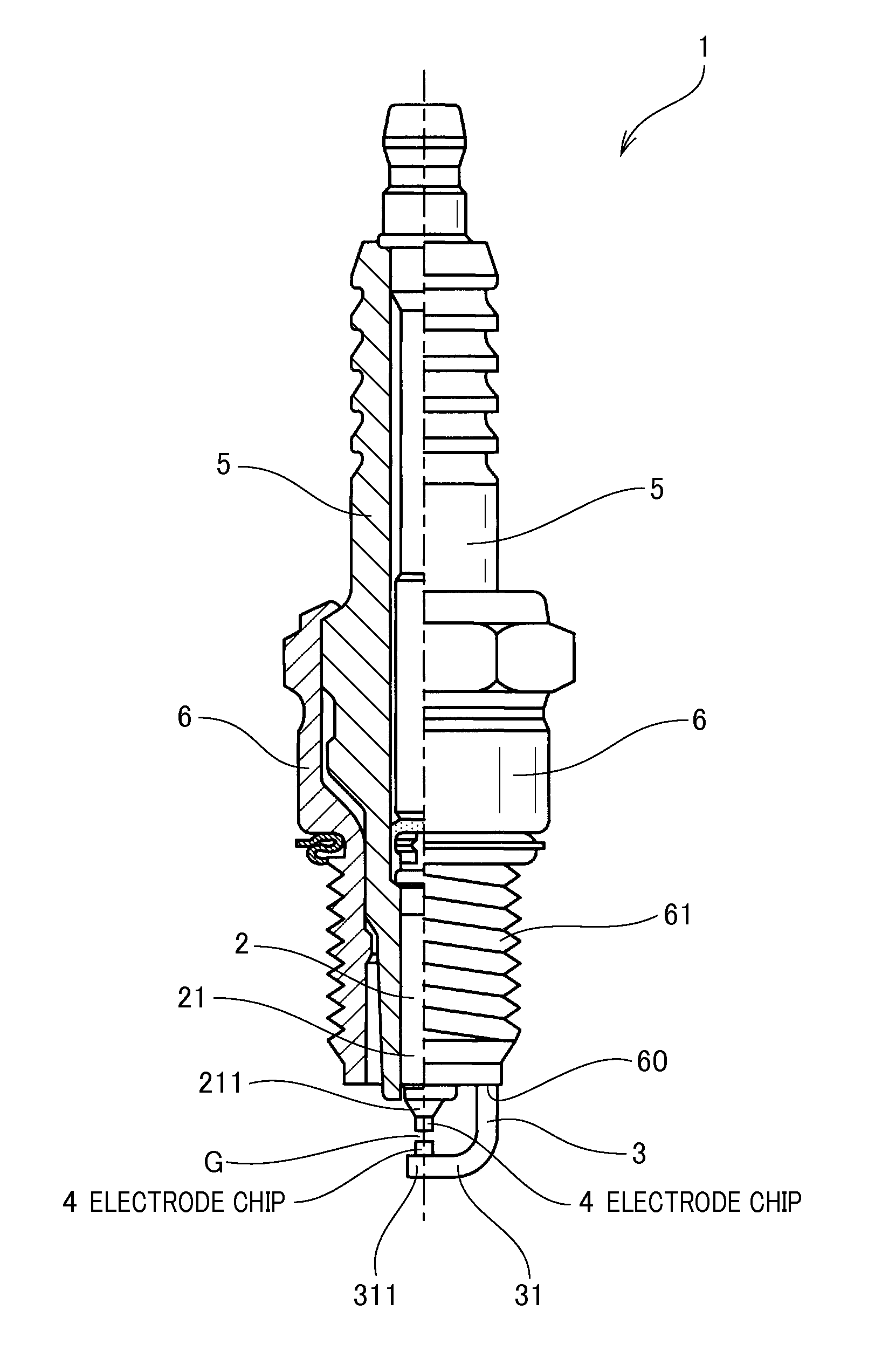
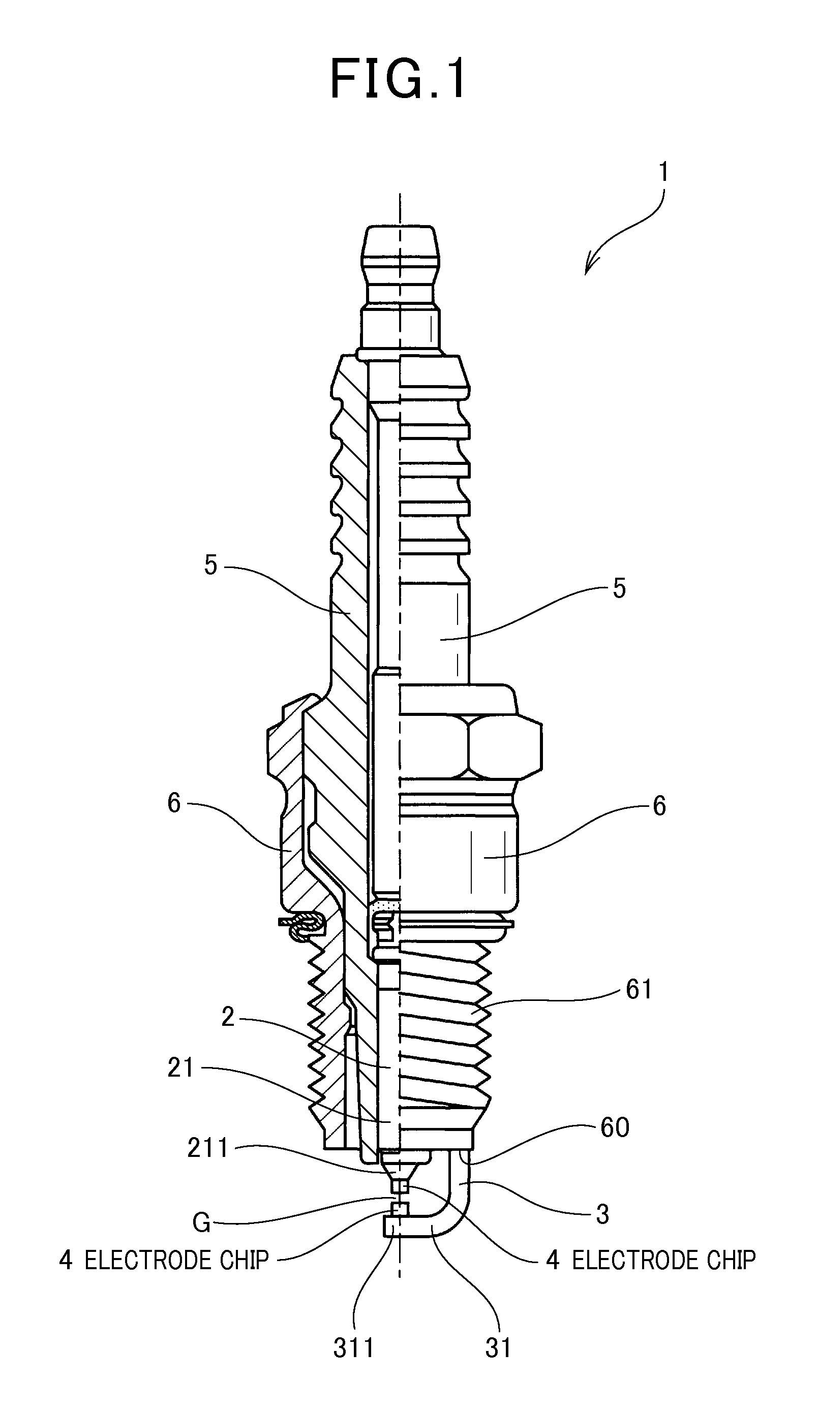
[0035]A description will be given of a spark plug 1 according to first and second exemplary embodiments to be used for internal combustion engines with reference to FIG. 1 and FIG. 2.

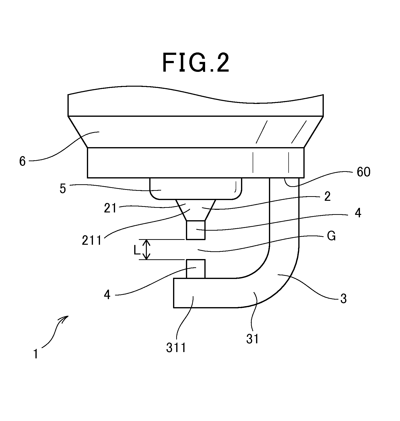
[0036]FIG. 1 is a view showing a cross section of a part of the spark plug 1 according to the first and second exemplary embodiments. FIG. 2 is a view showing a structure of a center electrode 2, an earth electrode 3, electrode chips 4 formed on the center electrode 2 and the earth electrode 4, and a spark discharging gap G in the spark plug according to the first and second exemplary embodiments shown in FIG. 1. In particular, the electrode chip 4 is formed on the center electrode 2. The electrode chip 4 is formed on the earth electrode 3. Those electrode chips 4 are faced to each other through the spark discharging gap G.

[0037]The electrode chip 4 is made of 40 to 60 mol % of aluminum and iridium as a remainder thereof.

[0038]A description will now be given of a detailed structure of each electrode chi...

second exemplary embodiment

[0051]A description will be given of the spark plug 1 according to a second exemplary embodiment. Each of the center electrode 2 and the earth electrode 3 in the spark plug 1 according to the second exemplary embodiment has the electrode chip 4 which is different in content from the electrode chip 4 used in the spark plug 1 according to the first exemplary embodiment.

[0052]That is, the spark plug 1 according to the second exemplary embodiment has the electrode chips 4, each of which is comprised of at least one metal selected from nickel, iron, cobalt, platinum and rhodium within a range of 1 to 20 mol %. That is, the electrode chip 4 in the spark plug 1 according to the second exemplary embodiment is comprised of 40 to 60 mol % of aluminum, 1 to 20 mol % of at least one type of metals selected from nickel, iron, cobalt, platinum and rhodium. The electrode chip 4 is further comprised of iridium as a remainder thereof.

[0053]Because other components of the spark plug 1 according to th...

third exemplary embodiment

[0055]A description will be given of a third exemplary embodiment. In the third exemplary embodiment evaluated the wear resistance of each of test samples as the spark plug. The wear resistance is composed of the spark discharging wear resistance and the oxidation resistance.

[0056]The third exemplary embodiment used a plurality of electrode chips having a different composition shown in Table 1. The third exemplary embodiment prepared test samples S1 to S21, each of which has an electrode chip having a different composition. The third exemplary embodiment detected the spark discharging wear resistance and the oxidation resistance of each of the test samples S1 to S21.

[0057]Further, Table 1 shows a composition, a ratio of an area of an intermetallic compound in the electrode chip in each of the test samples S1 to S21. Incidental impurity is omitted from Table 1.

[0058]A description will now be given of the electrode chip used in each of the test samples S1 to S21.

[0059]The electrode ch...


PUM


Abstract

A spark plug has a center electrode and an earth electrode. The center electrode is faced to the earth electrode so that a spark discharging gap is formed between the center electrode and the earth electrode. An electrode chip is formed on at least one of the center electrode and the earth electrode. The electrode chip has a composition comprised of 40 to 60 mol % of aluminum and iridium as a remainder thereof. In the composition of the electrode chip, it is possible to replace part of the iridium with 1 to 20 mol % of at least one metal selected from nickel, iron, cobalt, platinum and rhodium.

Description

CROSS-REFERENCE TO RELATED APPLICATION[0001]This application is related to and claims priority from Japanese Patent Applications No. 2012-181583 filed on Aug. 20, 2012 and No. 2013-59611 filed on Mar. 22, 2013, the contents of which are hereby incorporated by reference.BACKGROUND OF THE INVENTION[0002]1. Field of the Invention[0003]The present invention relates to spark plugs for use in internal combustion engines of motor vehicles.[0004]2. Description of the Related Art[0005]Internal combustion engines mounted to motor vehicles use various types of spark plugs in order to ignite a fuel in a combustion chamber. For example, a spark plug has a conventional structure in which a spark discharging gap is formed between a center electrode and an earth electrode. Spark discharge is generated in the spark discharging gap formed between the center electrode and the earth electrode in order to ignite a mixture gas composed of air and a fuel in the combustion chamber of the internal combustio...

Claims


Application Information

Patent Timeline
IPC IPC(8): H01T13/39
CPCH01T13/39
Inventor MURAYAMA, YUKIABE, NOBUODOI, YOSHINORITOMINE, TOSHIYUKIYOKOTA, SHUNSUKE
Owner DENSO CORP
Why Eureka
Try Eureka