Transmission

a transmission apparatus and drive train technology, applied in the direction of electric vehicles, transportation and packaging, electric devices, etc., can solve the problems of unnecessarily raising the center of gravity of the vehicle, inefficient transmission of drive torque, and disclosure of assembly, so as to simplify the assembly and disassembly of the transmission. , the effect of reducing the number of components

Active Publication Date: 2008-02-21
KORDEL ANTRIEBSTECHN
View PDF12 Cites 9 Cited by
  • Summary
  • Abstract
  • Description
  • Claims
  • Application Information

AI Technical Summary

Benefits of technology

[0010]An initial advantage of the invention is that the number of components used in the transmission is significantly reduced, since, for example, the drive wheel is directly connected in torque-proof fashion to the hollow gear and the hollow gear forms the main element of a transmission stage and the housing. Because the number of components is significantly reduced a substantially simplified assembly and disassembly of the transmission can be performed.
[0011]However, the main advantage of this invention is that the loads occurring on the vehicle are transferred directly from the frame of the vehicle into the transmission housing and from there directly through the hollow gear and its bell-shaped housing to the drive wheel, and the hollow gear and bell-shaped housing is further supported on a support element, which is a component of the housing. The transmission housing is directly connected to the frame of the vehicle through a lateral flange connection, so that the drive components are not impaired in their function through imposed loads, that is, they need only transfer torque.
[0012]In the preferred embodiment of the invention, the provided hollow gear element is formed within a bell-shaped housing which extends over and around its support element. The support element itself is a component of the housing or of a section of the housing and may comprise a central opening provided for receiving additional transmission components. The hollow gear and bell-shaped housing is supported upon the support element with bearing elements of conventional design. In such a manner, the hollow gear and bell-shaped housing assures a safe load reception and load transfer to the affixed drive wheel.
[0013]The transmission is preferably provided in two stages, wherein a first transmission stage is connected to the drive motor through a spur gear, while a second transmission stage is associated with the drive wheel through a drive gear in the nature of a planetary assembly which is only partially formed. Thereby, torque is transmitted according to the gear ratio, which can be adjusted for the application. This substantially increases the variability and thus also the utility of the transmission. According to requirements, a certain gear ratio can be selected by combining respective transmission stages with each other.
[0014]In an alternative embodiment, a pinion is provided in connection with the housing support element. The pinion is disposed co-axial to the rotation axis of the drive wheel, and can be housed within a central opening of the support element of the housing. Pinion positioning connection can be performed through pressing it in, or through bolting it on. It is also possible that the pinion may be integrally formed with the housing, or the housing component. Conventional bearing elements are then mounted circumferentially to the shaft of the pinion and support the hollow gear and bell-shaped housing. One and preferably several roller bearings are provided adjacent the pinion in order to support the hollow gear and bell-shaped housing. By supporting the hollow gear and bell-shaped housing in this fashion, transfer of the vehicle load to the drive wheel is accomplished and transferred loads to the other transmission components is avoided.
[0015]The bearing elements are fixed in position by lock washers or retaining rings proximal to the support element. Distal to the support element, the bearing elements abut a support shoulder of the hollow gear and bell-shaped housing and are retained by lock washers or retaining rings adjacent the pinion.

Problems solved by technology

The assembly disclosed in the '174 patent inefficiently transfers drive torque, in part because the rotational axis of the electric motor and its drive shaft is normal to the rotational axis of the drive wheel.
Additionally, the physical size of the transmission makes the component cumbersome and, as substantial components are mounted relatively high from the floor, unnecessarily raises the center of gravity of the vehicle.
Finally, the transfer of the loads to the running wheels is not performed in an optimum manner, in part because the assembly requires a drive shaft at least the length of the radius of the electric motor's armature stack.

Method used


Image

  • Transmission
  • Transmission
  • Transmission

Examples


Embodiment Construction

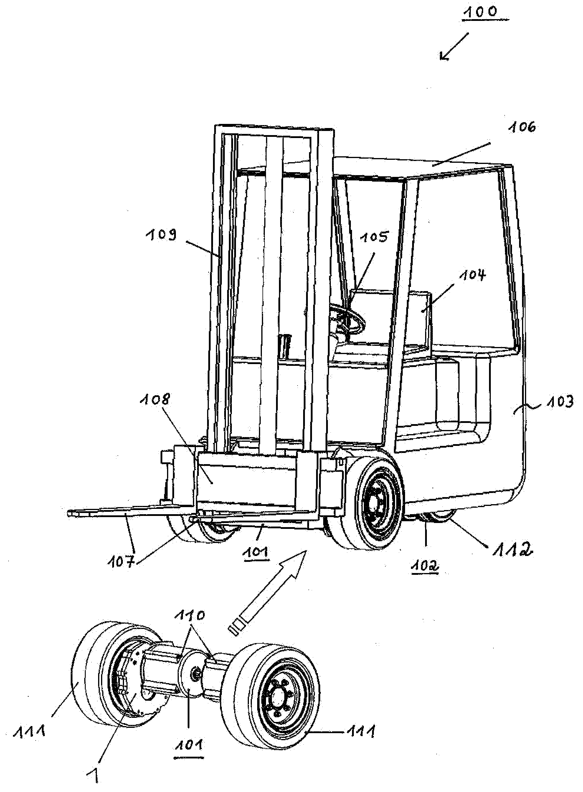
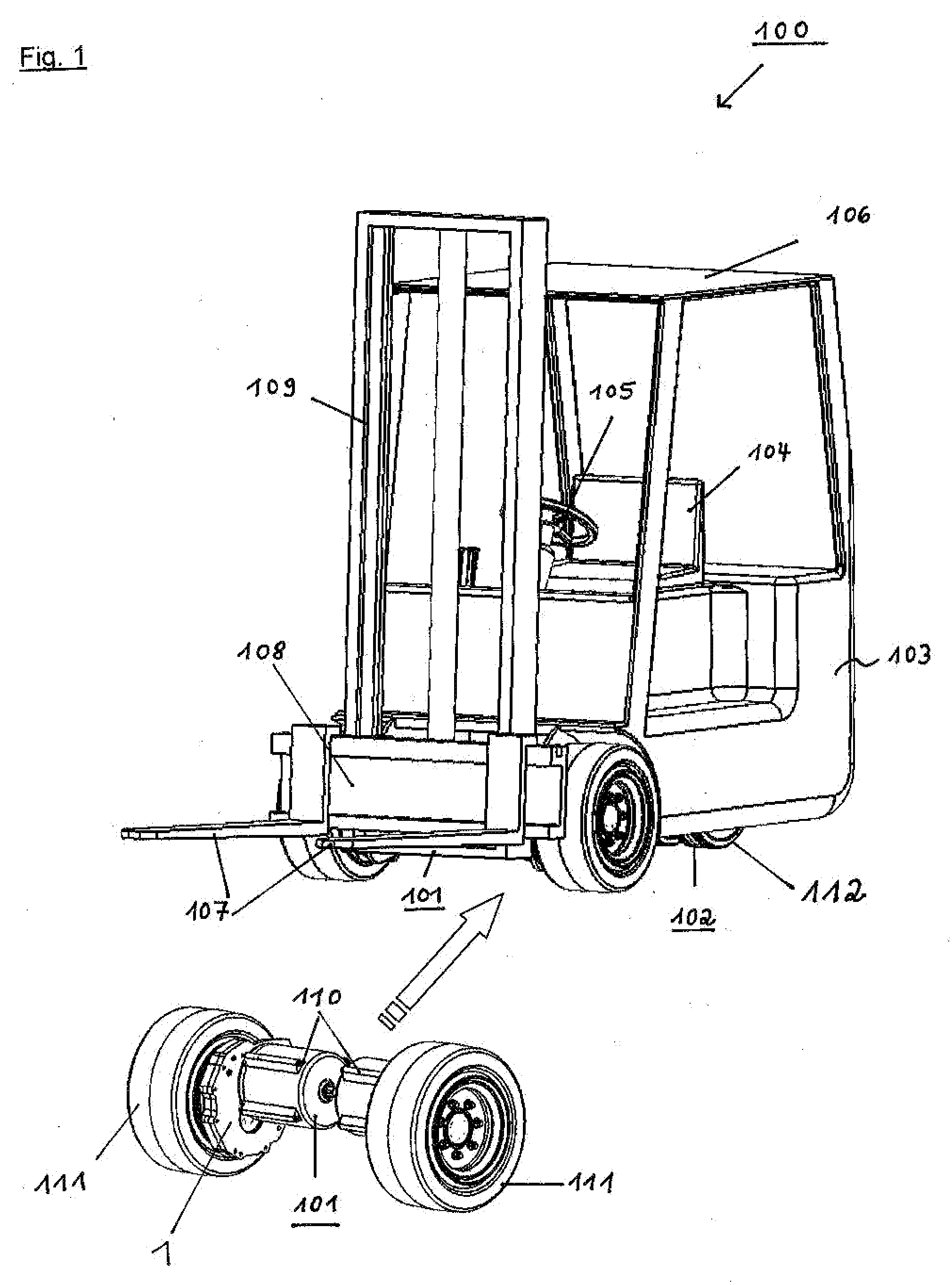
[0026]FIG. 1 shows a floor transport vehicle 100 in a perspective view with a front axle 101 and a rear wheel steering apparatus 102, of which only the attached running wheels 112 are shown. The floor transport vehicle 100 has a box shaped superstructure 103, with a driver seat 104, and a steering wheel 105. A superstructure 106 is provided above the box shaped superstructure 103 for driver protection, the superstructure 106 being open on all sides but closed in the upper section. Two forks 107 are used for lifting loads, wherein the distance between each can be adjusted on a carrier 108. The carrier 108 can be adjusted in elevation along a frame 109, whereby lifting loads is possible. For driving the floor transport vehicle 100, two electric drive motors 110 each with a transmission 1, and associated drive wheel 111, are provided. The steering of the floor transport vehicle is performed through the steering wheel 105, which is in direct operating engagement with a steerable rear ax...


PUM


Abstract

A transmission (1), preferably for a front axle of a floor transport vehicle (100), comprises at least one transmission stage, a drive sprocket (6), a hollow gear (4, 203), and a housing, wherein the drive sprocket (6) and the hollow gear (4, 203) each have a rotation axis, which axes are parallel and disposed offset from each other. A drive wheel (111) is connected in torque-proof fashion with the hollow gear and housing (4, 203) and the drive sprocket (6) is coupled to a drive motor (25). The motor is mounted to the transmission (1) through a flange. Assembly and disassembly of the transmission is simplified by the relatively few component parts of the transmission. Further, vehicle loads are efficiently transferred to the drive wheel by supporting the hollow gear (4, 203) rotatably upon a fixed support element (13) forming a section of the housing, wherein the support element (13) is disposed coaxial with the rotation axis of the hollow gear (4, 203).

Description

RELATED APPLICATIONS[0001]This application claims priority from, and incorporates by reference, German patent application serial No. DE 10 2006 038 396.6, filed Aug. 15, 2006BACKGROUND[0002]1. Field of the Invention[0003]The invention relates to a drive train transmission apparatus, preferably for a front axle of a floor transport vehicle with at least one transmission stage, comprising a housing, a drive sprocket, wherein the drive sprocket is coupled with a drive motor which is fixed to the transmission housing, a hollow gear, wherein the rotational axis of the drive sprocket and the hollow gear are disposed offset from each other, and a running wheel fixed in a torque-proof fashion with the hollow gear.[0004]2. Introduction[0005]Transmissions of the kind disclosed herein are typically required for drive wheels for floor transport vehicles. Such transmissions must preferably be built as small as possible, and additionally have to be suitable for carrying large loads. In order to a...

Claims


Application Information

Patent Timeline
Patent Type & Authority Applications(United States)
IPC IPC(8): B60K17/00
CPCB60K7/0007B60K17/043B60L2220/46B60K2007/0038B60K2007/0061B60K17/046
Inventor RAUE, JOSEF
Owner KORDEL ANTRIEBSTECHN
Why Eureka
Try Eureka