
Self-excitation of switched reluctance generators during load bus faults

a switched reluctance generator and load bus technology, applied in the direction of electric generator control, motor/generator/converter stopper, dynamo-electric converter control, etc., can solve the problem of load fault, generator output voltage drops to zero, load fault can occur, etc., to achieve the effect of reducing weigh

Inactive Publication Date: 2008-02-21
HAMILTON SUNDSTRAND CORP
View PDF6 Cites 11 Cited by
  • Summary
  • Abstract
  • Description
  • Claims
  • Application Information

AI Technical Summary

Benefits of technology

[0011]In the event of a load bus fault, the present invention provides a method of utilizing a portion of the current from one phase of the switched reluctance generator to provide the requisite excitation energy while the remaining phases deliver energy to the faulted positive bus as required. This eliminates the need for a battery or other auxiliary generator. This invention thus provides both weight reduction and reliability improvement. In addition, even though this generator relies on a capacitor bank for excitation energy under normal operating conditions as in the prior art, the problem of the prior art where once the capacitor bank is discharged the generator can no longer operate, is avoided. Unlike the prior art the capacitor bank is never fully discharged. In addition, this generator may also be used a motor. Due to this dual functionality as either a generator or a motor, it is common to refer to a switched reluctance generator as a switched reluctance machine.

Problems solved by technology

A load fault can occur when the maximum load current for a particular generator system is exceeded.
A load fault would typically happen not in the generator itself but somewhere in the load that it is powering.
If a fault occurs, the output voltage of the generator drops to zero.
During such a load fault, current from the generator is still needed to operate protective devices such as circuit-breakers and fuses.
In the event of a short-circuit or load fault, the generator still requires excitation energy to provide current for protective devices, however because of the short-circuit or fault condition, the generator can no longer use its DC output as a source of this energy.
Without the necessary excitation energy to sustain the generator in the event of a fault, the entire system would simply discharge and stop producing power.
A drawback of this conventional setup is that once the capacitor bank discharges, it can no longer excite the switched reluctance generator to operate, because the capacitor bank has been discharged to zero volts.
Although this overcomes the earlier problem, it introduces additional problems.
One drawback to this solution is overall diminished reliability due to the increased complexity and the need for additional hardware.
Another drawback is an increase in the overall weight of the generator, which is undesirable in aerospace applications, due to the additional power source.

Method used


Image

  • Self-excitation of switched reluctance generators during load bus faults
  • Self-excitation of switched reluctance generators during load bus faults
  • Self-excitation of switched reluctance generators during load bus faults

Examples


Embodiment Construction

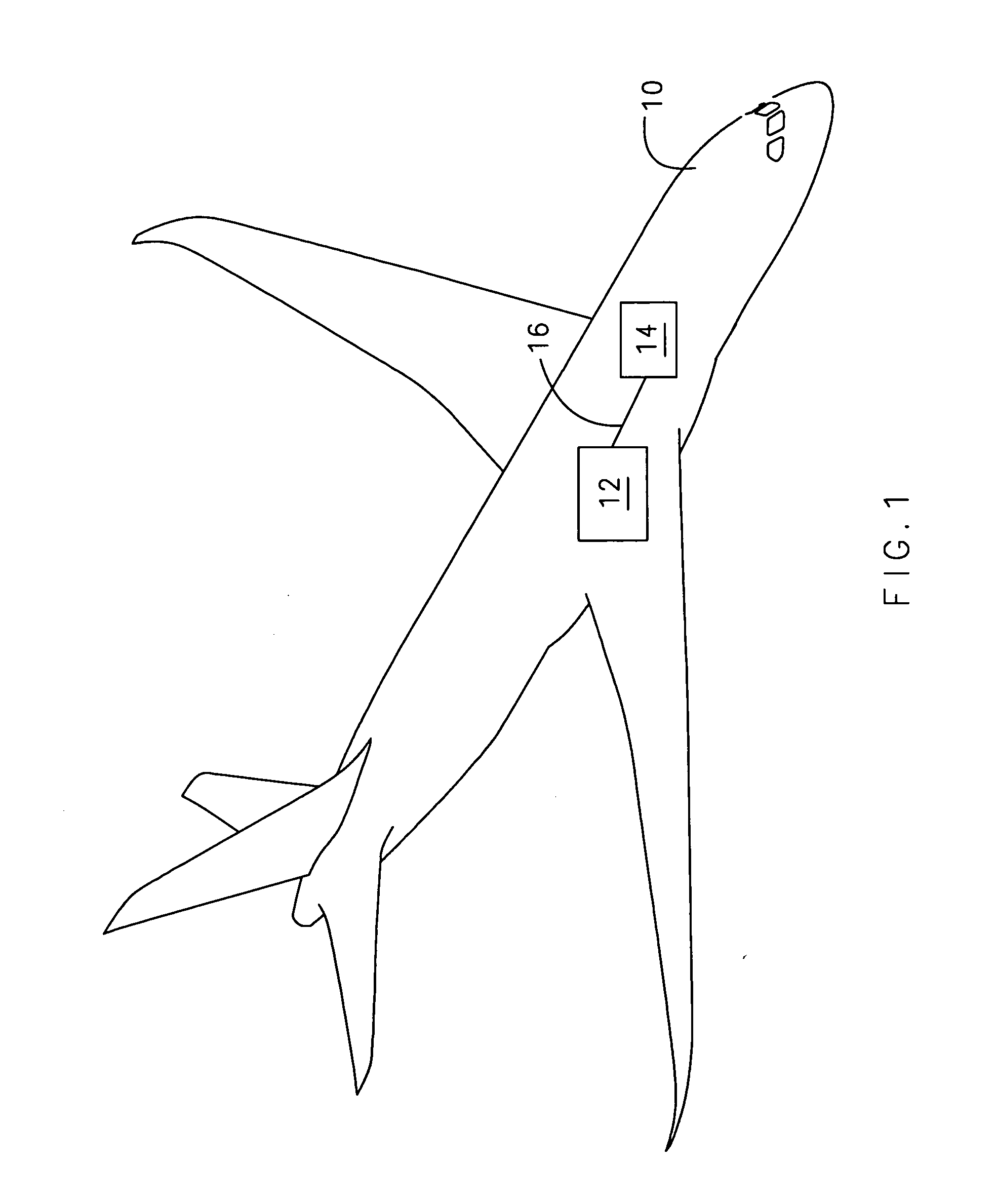
[0016]FIG. 1 schematically shows the present invention in an example environment of an aircraft 10. The aircraft 10 comprises a switched reluctance generator 12, a load 14, and a connection 16. Depending on the size and type of the aircraft, numeral 12 might represent a plurality of switched reluctance generators. Load 14 represents any device in the aircraft that requires electricity. The generator 12 is connected to the load 14 by the connection 16. The connection 16 represents both a positive and a negative bus of the generator 12. Although FIG. 1 shows an aircraft, this invention is not limited to use in an aircraft. FIG. 1 is merely presented to show one use of the present invention.

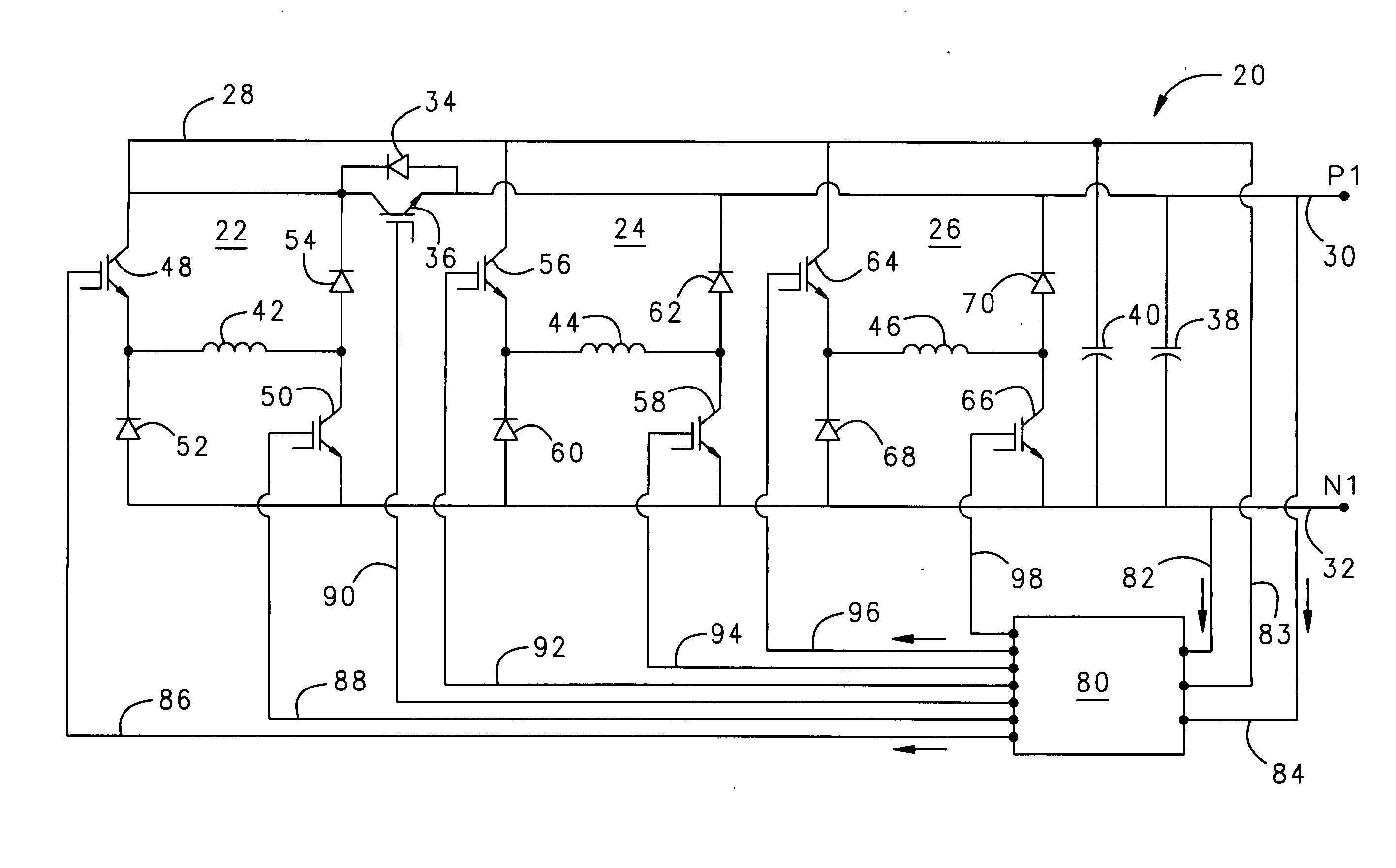
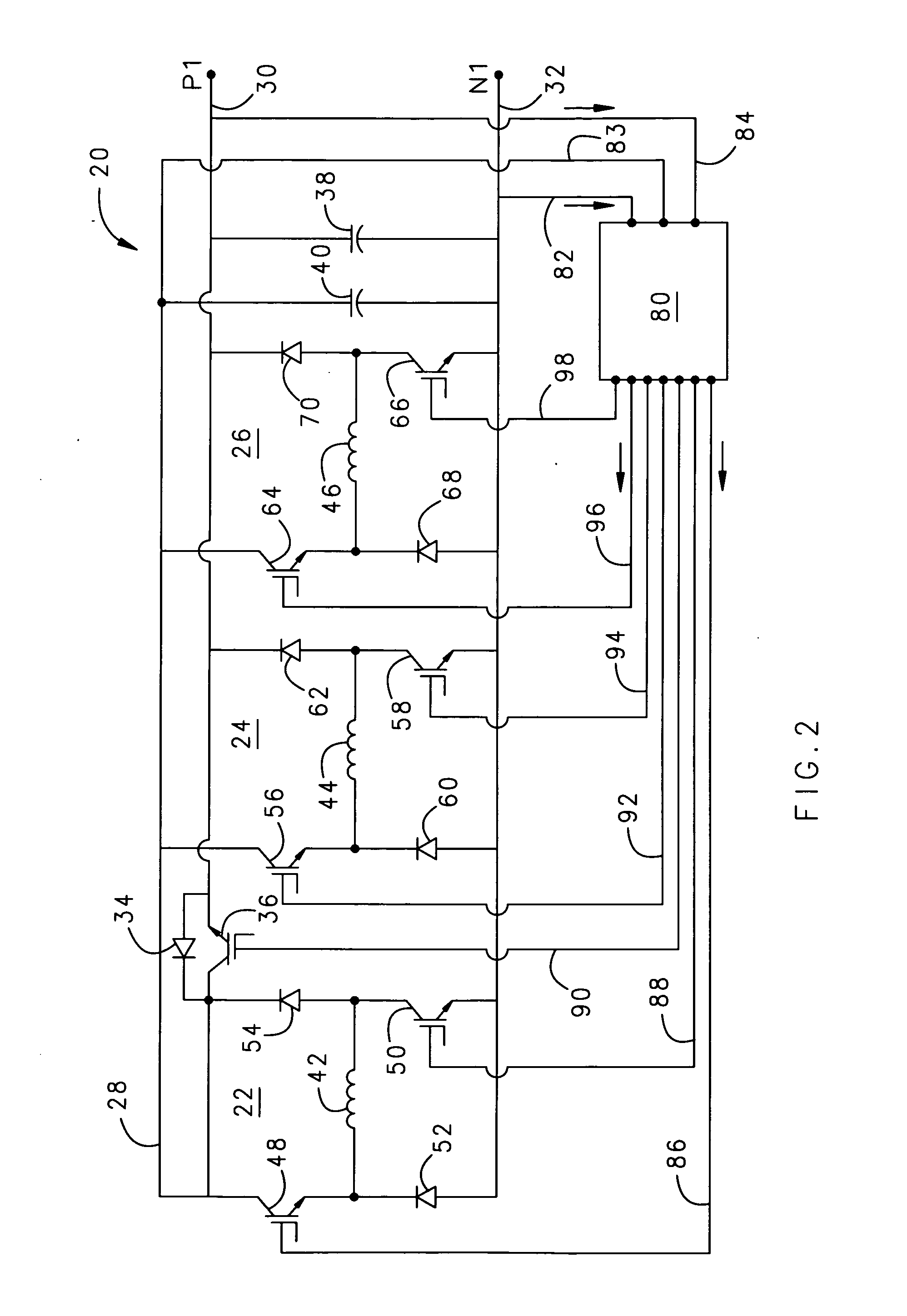
[0017]FIG. 2 shows circuit 20 for a switched reluctance generator, comprising three phases 22, 24, and 26. An alternative embodiment could include additional phases. Each phase includes an inductive winding, two switches, and two diodes. While it is possible that each phase might comprise just one s...


PUM


Abstract

A self-excited, switched reluctance generator obtains excitation energy from a capacitor bank via an excitation bus during normal operation. During a short-circuit or load fault, one or more phases of the generator provide power to the excitation bus while the remaining phases send current to a faulted positive bus. The system does not require an external battery or power source for excitation energy. The system is capable of resuming normal operation after the load bus fault.

Description

BACKGROUND OF THE INVENTION[0001]This invention generally relates to self-excitation of a switched reluctance generator during a short-circuit or load bus fault without the need for a battery or auxiliary DC power source.[0002]Switched reluctance electric generators are often used in aerospace applications, where they typically provide electrical power for the vehicle in which they reside. In such aerospace applications, a generator must be able to provide current during short-circuit and fault conditions on a positive load bus.[0003]A load fault can occur when the maximum load current for a particular generator system is exceeded. A common type of load fault is a short circuit, which is an accidental low-resistance connection between two nodes of a circuit that are meant to be at different voltages. A load fault would typically happen not in the generator itself but somewhere in the load that it is powering. If a fault occurs, the output voltage of the generator drops to zero. Duri...

Claims


Application Information

Patent Timeline
IPC IPC(8): H02P1/46
CPCH02P9/102H02P2101/30H02P29/022H02P9/107H02P29/032
Inventor TANDON, PIYUSH
Owner HAMILTON SUNDSTRAND CORP
Learn More