
Surge Voltage Protection Device with Improved Disconnection and Visual Indication Means

Inactive Publication Date: 2008-02-21
ABB FRANCE SAS
View PDF1 Cites 22 Cited by
  • Summary
  • Abstract
  • Description
  • Claims
  • Application Information

AI Technical Summary

Benefits of technology

[0027] Consequently, the features provided by the invention seek to provide a remedy to the various drawbacks listed above and to propose a novel device for protecting electrical installations against voltage surges, which device guarantees disconnection of the protection component in a manner that is particularly reliable and fast.
[0029] Another feature of the invention seeks to provide a novel device for protecting electrical installations against voltage surges, which device is of a design that is particularly simple and inexpensive.

Problems solved by technology

When a surge occurs within the installation, the varistor is subjected to a current shock that has the effect of degrading it and causing it to heat up, making thermal disconnection thereof necessary.
The degradation of a varistor is difficult or impossible to predict, insofar as it depends not only on the number of current shocks the varistor has suffered over its lifetime, but also on their amplitude.
Consequently, it is difficult to predict, a priori, the lifetime and the degree of aging of a varistor, and users often discover a posteriori that the varistor has been destroyed, such that the installation runs the risk of operating without any protection during some length of latency time.
Unfortunately, it can happen that the slider or the indicator is impeded in its movement, in particular when the slider and / or the indicator are poorly dimensioned or if the guide means are defective, thus leading to the slider being poorly guided.
In this situation, the slider and / or the indicator can impede or even prevent disconnection of the varistor.
Nevertheless, such a measure presents the drawback of weakening the soldered connection between the disconnector blade and the corresponding electrode of the varistor.
In general, the mechanical complexity of known devices requires the operations of manufacturing the parts to be very well controlled, thereby significantly increasing the cost of manufacturing such devices.

Method used


Image

  • Surge Voltage Protection Device with Improved Disconnection and Visual Indication Means
  • Surge Voltage Protection Device with Improved Disconnection and Visual Indication Means
  • Surge Voltage Protection Device with Improved Disconnection and Visual Indication Means

Examples


Embodiment Construction

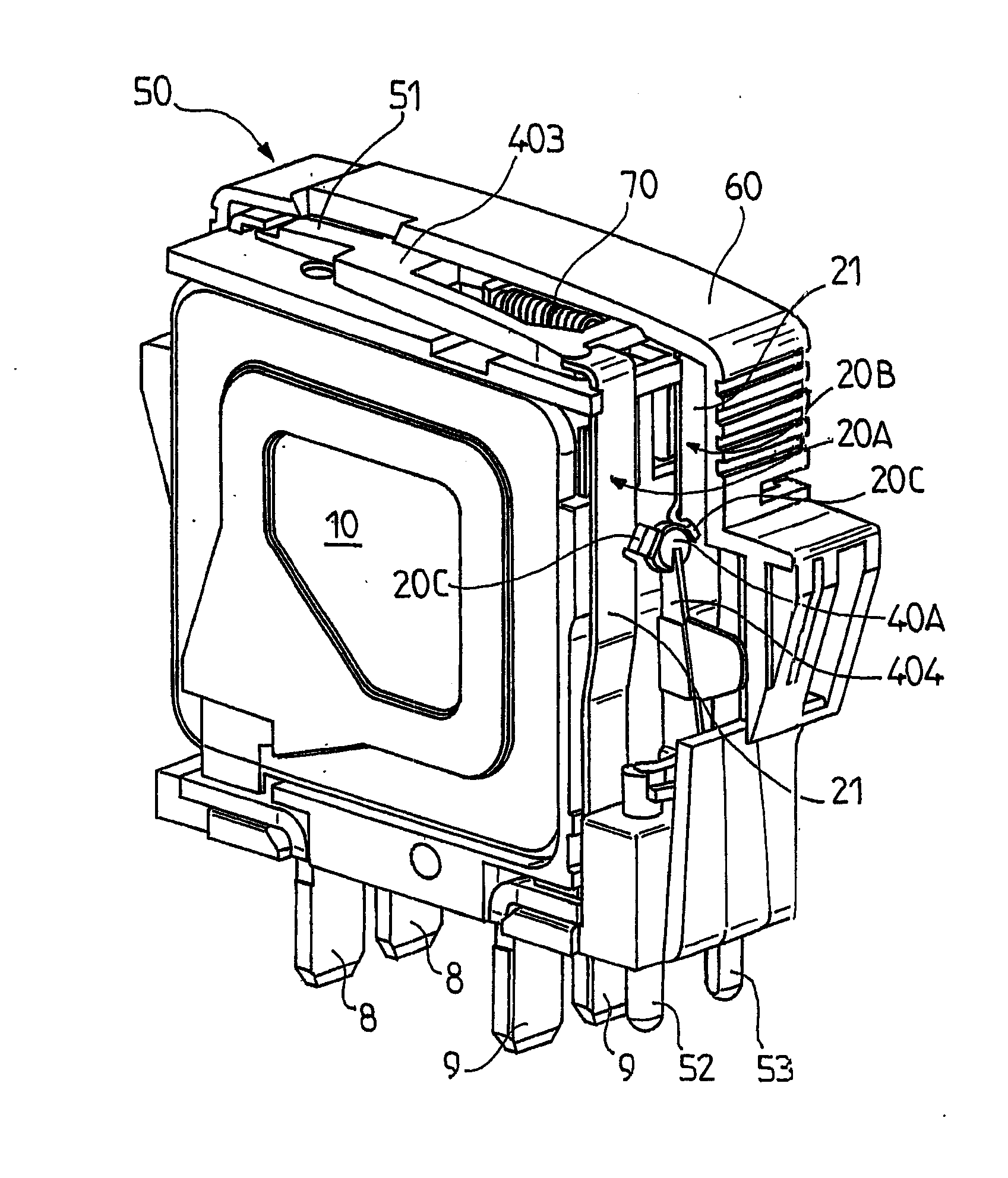
[0054] The device of the invention for providing protection against voltage surges is designed to be connected in parallel with the electrical equipment or the installation to be protected. The term “electrical installation” refers to any type of apparatus or network that might be subjected to voltage disturbances, in particular to transient voltage surges due to lightning. Under such circumstances, the device is thus formed by a lightning arrestor.

[0055] The device of the invention for providing protection against voltage surges is advantageously designed to be placed between one of the phases of the installation that is to be protected and ground.

[0056] Without going beyond the ambit of the invention, it is also possible to envisage that instead of being connected in parallel between one of the phases and ground, the device is connected between neutral and ground, between a phase and neutral, or between two phases (for differential protection).

[0057] The protection device compr...


PUM


Abstract

A device for protecting an electrical system against surge voltages, comprising one or more protection components (10), means (20) for disconnecting the protection component (10) and means (30) for visually indicating the state of the component (10), operationally connected to the disconnection means (20) and comprising at least one control part (40) and at least one means (50) for indicating the state of the protection component (10), combined with the control part (40), whereby the relative arrangement of the control part (40) and the disconnection means (20) is such that, when the disconnection means are opened (20), the disconnection means release the control part (40), thereby allowing the control part to move.

Description

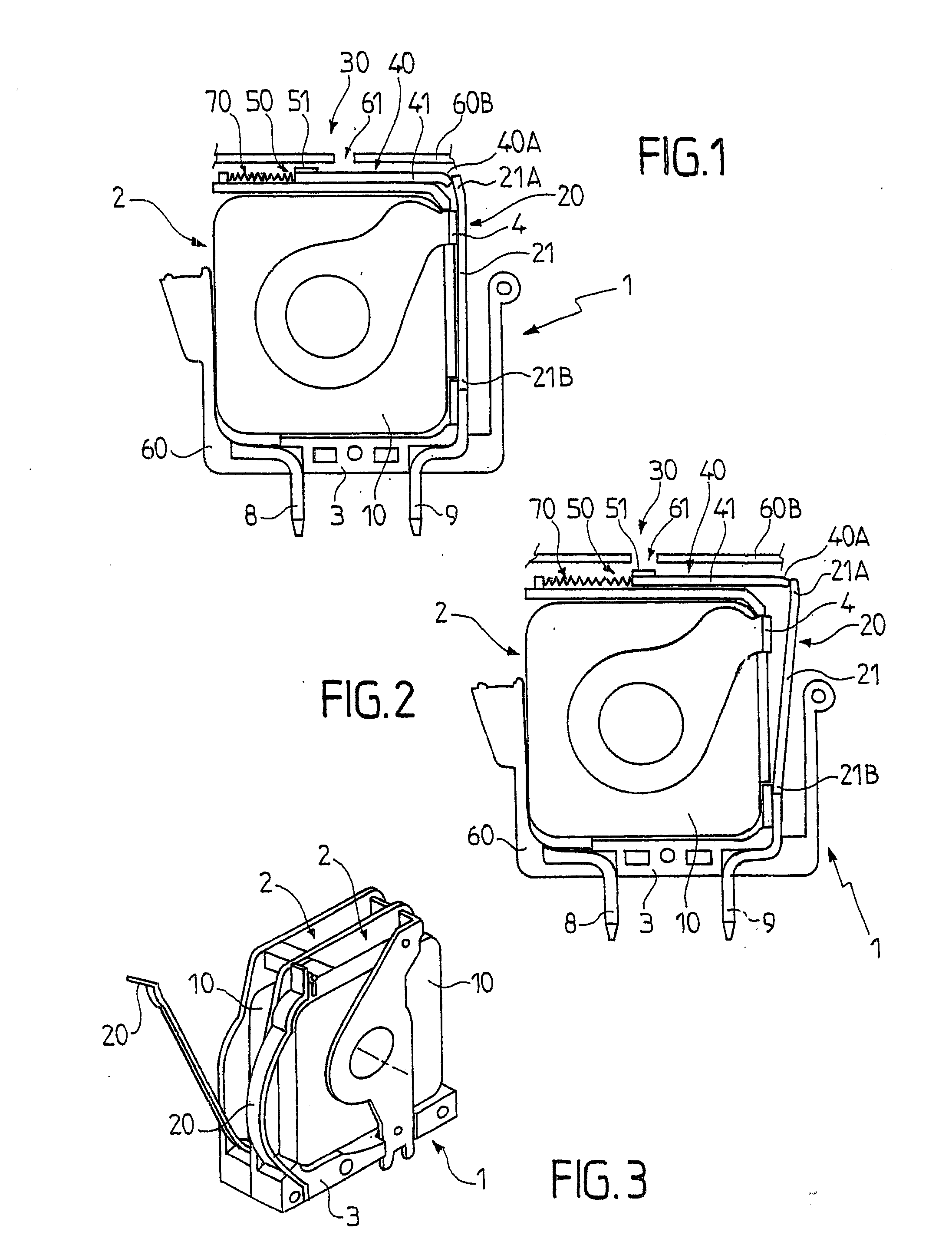
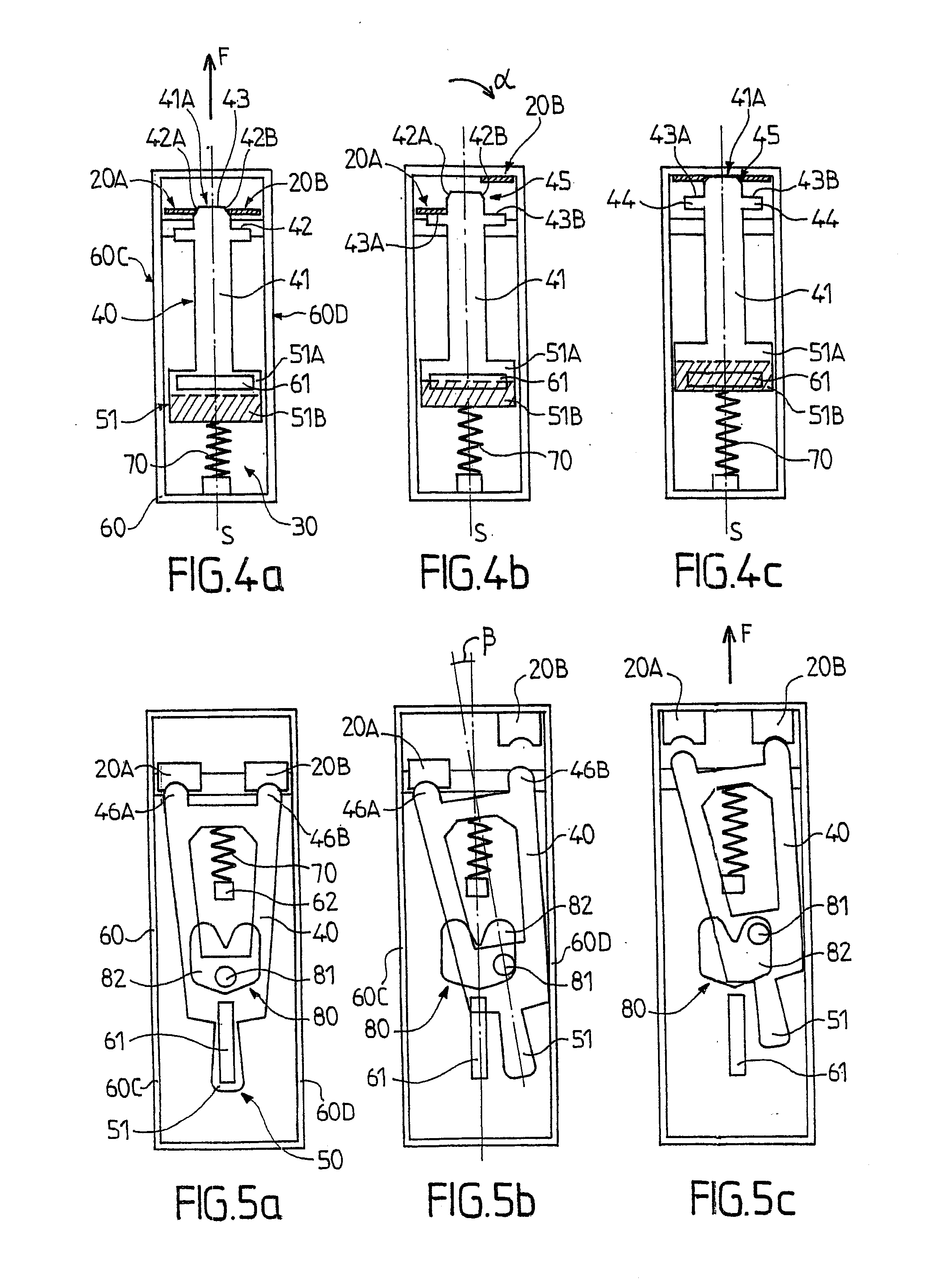
FIELD OF THE INVENTION [0001] The present invention relates to devices for protecting electrical installations and equipment against transient electrical voltage surges. [0002] More particularly, the present invention relates to a device for protecting an electrical installation against voltage surges, the device comprising: [0003] at least one protection component; [0004] disconnector means for disconnecting the protection component, adapted to disconnect it from the electrical installation and suitable for moving between a closed position in which the protection component is connected, and an open position in which the protection component is disconnected; and [0005] indicator means for indicating the state of the protection component, functionally connected to the disconnector means, and comprising: [0006] at least one control part distinct from the disconnector means and suitable for moving under the dependency thereof; and [0007] at least one indicator for indicating the state ...

Claims


Application Information

Patent Timeline
IPC IPC(8): H02H3/22H02H3/00H01C7/12H01T1/12
CPCH01T1/12H01C7/126
Inventor DONATI, MICHEL GEORGES JEANLAGNOUX, ALAIN RENE ROBERTBRUA, BERTRAND
Owner ABB FRANCE SAS
Learn More