Supercharge Your Innovation With Domain-Expert AI Agents!

Working machine

a technology for working machines and working tools, applied in the field of working machines, can solve the problems that the spindle head did not succeed in safely discovering the risk of a jammed chip, and achieve the effect of high accuracy of the position of the testing tool

Active Publication Date: 2008-02-21
GROB WERKE & K G
View PDF8 Cites 7 Cited by
  • Summary
  • Abstract
  • Description
  • Claims
  • Application Information

AI Technical Summary

Benefits of technology

[0023]It is actually possible that very slight deformations of the spindle head can be tolerated, as these deformations do not yet lead to an unacceptable quality of machining. This means that within an acceptance interval the shape of the spindle head, even if it differs from the ideal shape, is accepted, and machining the work piece by the working machine is not interrupted. Therefore the monitoring device has cleverly an additional evaluating device, and it is then based on its evaluation whether a machining is carried out or not.
[0025]The invention comprises furthermore not only a working machine as described, but the object according to the invention is also solved by a method for operating a working machine, where, first of all, a machining tool is set in the spindle head and is clamped there, then the shape of the spindle head is determined by the measuring device, the determined shape is evaluated by an evaluating device, and, if the shape is within an interval of acceptance, the machining of the work piece by the machining tool is carried out, or, if the shape is outside the interval of acceptance, the machining tool is removed from the spindle head, and at least the machining tool holding device in the spindle head is cleaned, in particular blown out. Through the method suggested by the invention a testing step is carried out which, on the one hand, determines in a measuring step determines the shape of the spindle head, and then, in an evaluation step tests whether the determined shape is acceptable, that means within an interval of acceptance which can be chosen in any way, if necessary, or whether it is outside of this interval of acceptance. If the determined shape is outside the interval of acceptance a further use of the working machine carries the risk of faulty machining, and it is then provided that the machining tool is removed again from the machining tool holding device of the spindle head, and then the holding device is cleaned. During the cleaning step then the chip or other impurities have to be removed, cleverly the tool holding device is blown out here or, if necessary, also rinsed with cooling or rinsing liquid. After that setting-in of the machining tool in the spindle head as well as the measuring or evaluating step is repeated one more time, and then machining is carried out if the shape is acceptable. If an acceptable shape still cannot be determined, by means of the control another rinsing can be provided or a superior error message is edited which leads to a corresponding checking of the working machine. The result is a very comprehensive protection against faulty machining and avoidable rejection by the suggestion according to the invention.
[0027]It is decisive with the invention not to determine the exact shape of the spindle head, but to confirm whether a chip or other impurities are clamped in such a way so that this cannot lead to faulty machinings.

Problems solved by technology

As already described in the state of the art measurements which monitor the correct close contact of the tool shank with the spindle head did not succeed in safely discovering the risk of a jammed chip.
However, such a jammed chip leads to a deformation (for example radial) of the spindle head which can be monitored.

Method used


Image

  • Working machine
  • Working machine

Examples


Embodiment Construction

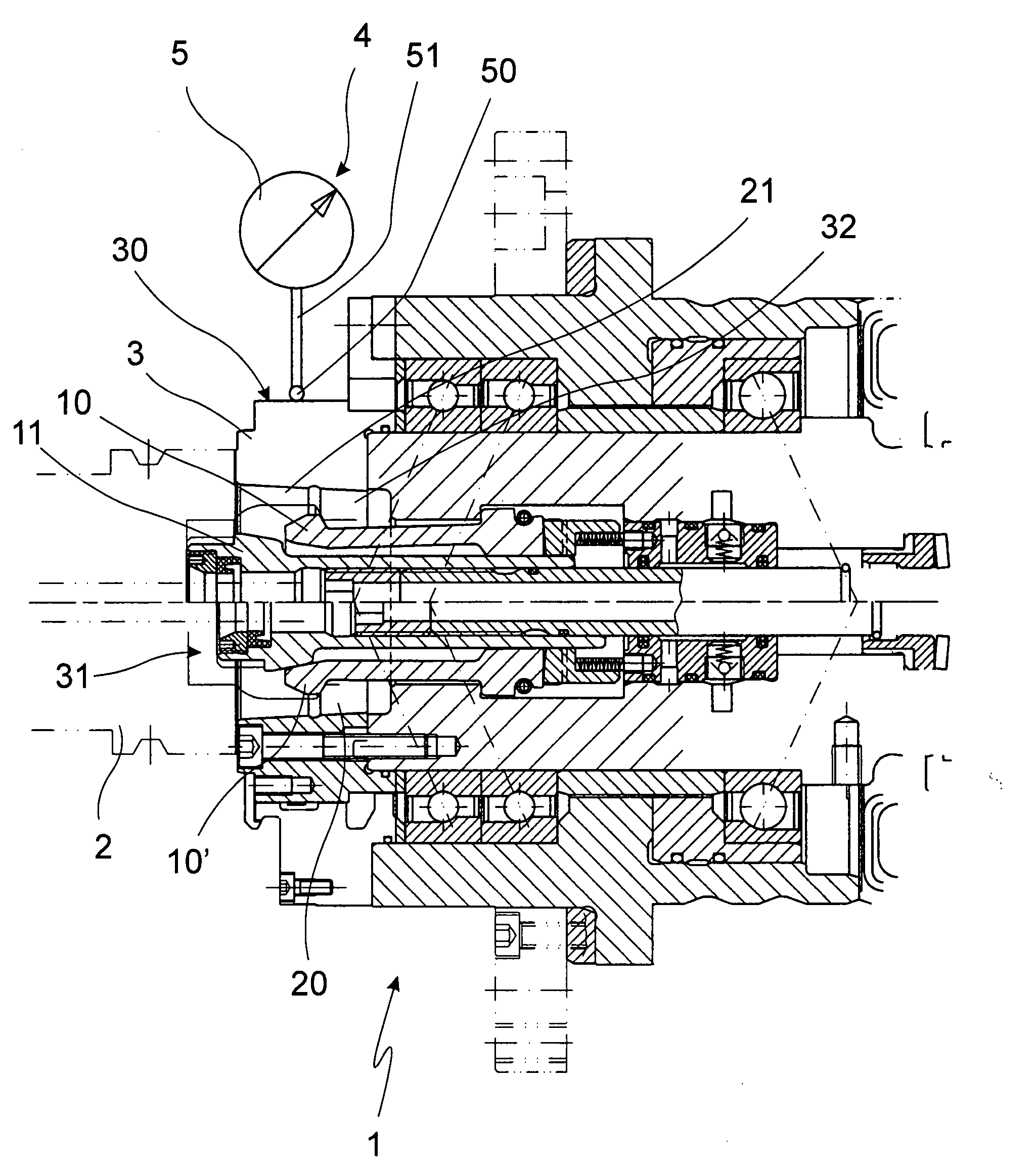
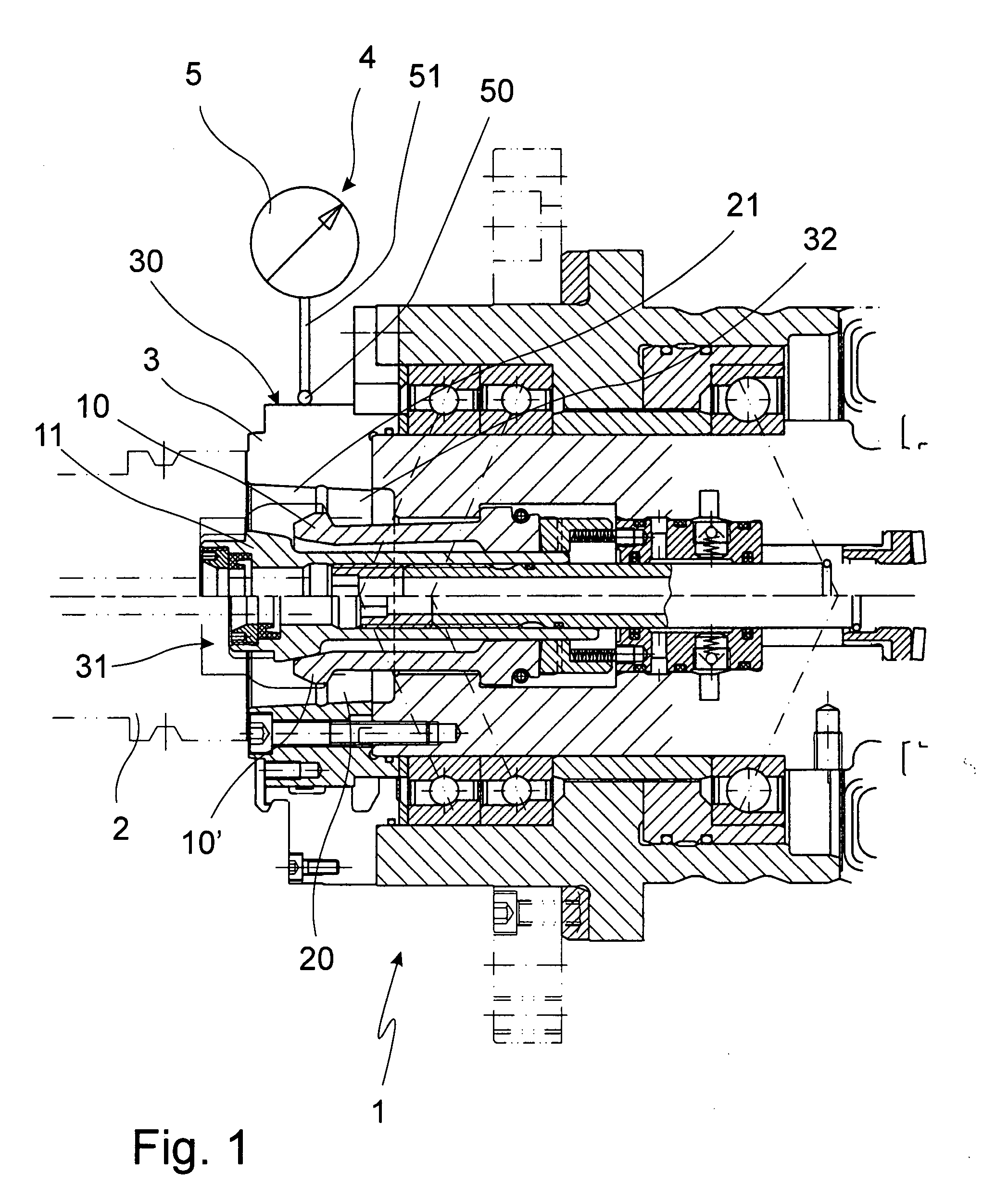
[0031]FIG. 1 shows the front part of the working spindle 1 facing a not-shown work piece. At its front end the working spindle 1 carries on its spindle head 3 the machining tool 2. So-called hollow shank cone tools are known which are held by a clamping claw 10, 10′. In the clamped position of the clamping claw 10′ the tool shank 20 is held in machining tool holding device 31 of the spindle head 3.

[0032]The exterior surface 21 of the tool shank is, if possible with the complete surface, in close contact with the interior surface 32 of the holding device of the spindle head. A chip in this region leads to a measurable deformation of the spindle head 3, in particular of its surface area or circumferential surface 30.

[0033]A measuring device 5 has a probe 50 or sensor 50 which monitors the shape of the spindle head 3 and the contour of the surface of the circumferential surface 30, which here has the same effect. The probe 50 or sensor 50 has a measuring line 51 in order to connect the...


PUM

PropertyMeasurementUnit
shapeaaaaaaaaaa
surface areaaaaaaaaaaa
pressureaaaaaaaaaa

Abstract

The invention refers to a working machine with a machining tool which can be set in a spindle head of a working spindle. A monitoring unit is provided which monitors the shape of the spindle head.

Description

[0001]The invention refers to a working machine with a machining tool which can be set in a spindle head of a machining spindle.BACKGROUND OF THE INVENTION[0002]Working machines of the type mentioned before are used, for example, for the cutting machining of work pieces, for example in machining centers, machining stations or also in transfer lines. A high degree of machining accuracy is demanded of the working machines mentioned before.[0003]The machining is carried out by machining tools which are set into rotation and positioned by machining spindles. By the cutting machining in the working room chips are whirled around which may be deposited at very different spots.[0004]When a machining tool is changed there is the risk that impurities or chips may get in the spindle head of the machining spindle, between the tool shank and the tool holding device which may still allow clamping the machining tool in the machining spindle, however, interfere with the high machining accuracy whic...

Claims


Application Information

Patent Timeline
Patent Type & Authority Applications(United States)
IPC IPC(8): B23Q15/22
CPCB23Q17/2225Y10T409/30392Y10T409/3084Y10T409/303752Y10T409/304088Y10T409/304312Y10T408/165Y10T409/308064Y10T409/307224Y10T408/76Y10T409/309408
Inventor MARTENS, KNUT
Owner GROB WERKE & K G
Features
  • R&D
  • Intellectual Property
  • Life Sciences
  • Materials
  • Tech Scout
  • Unparalleled Data Quality
  • Higher Quality Content
  • 60% Fewer Hallucinations
Learn More