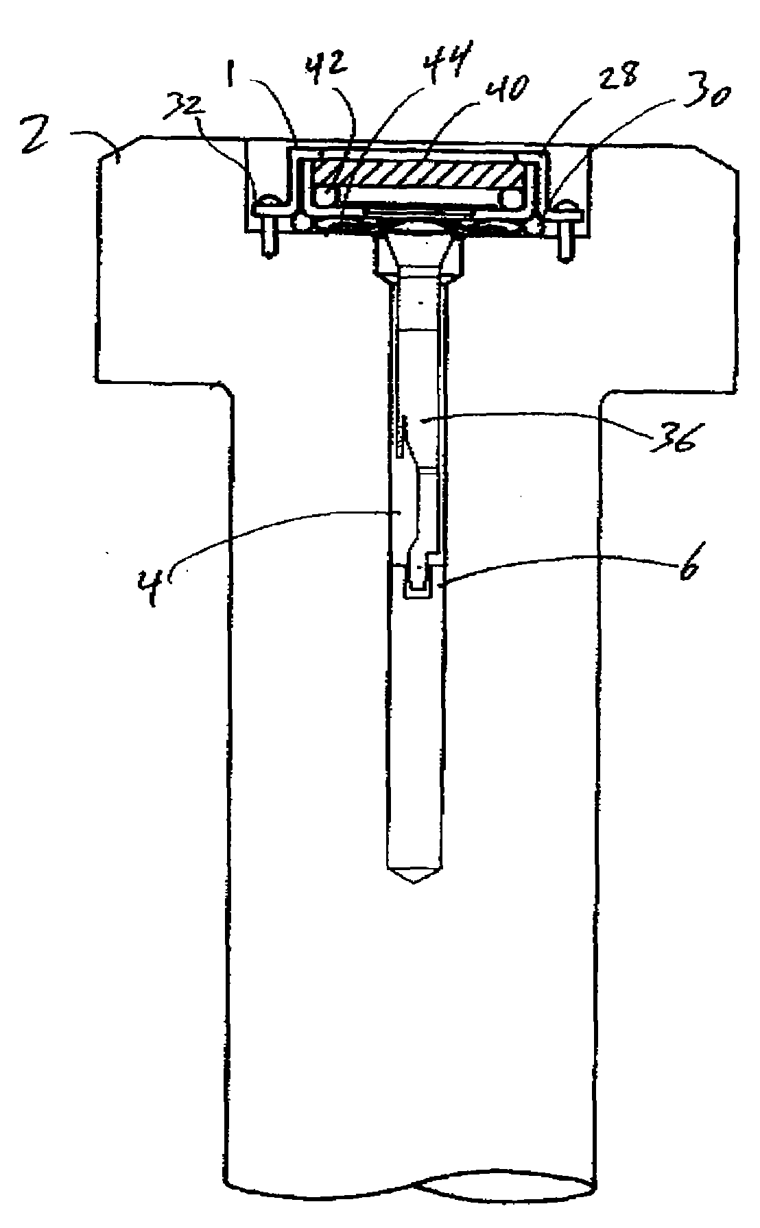
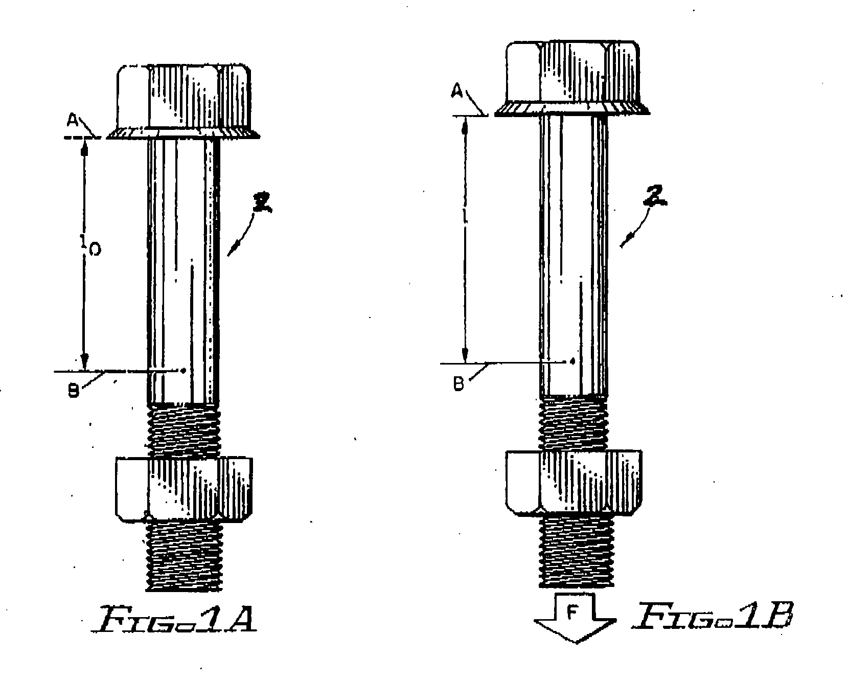
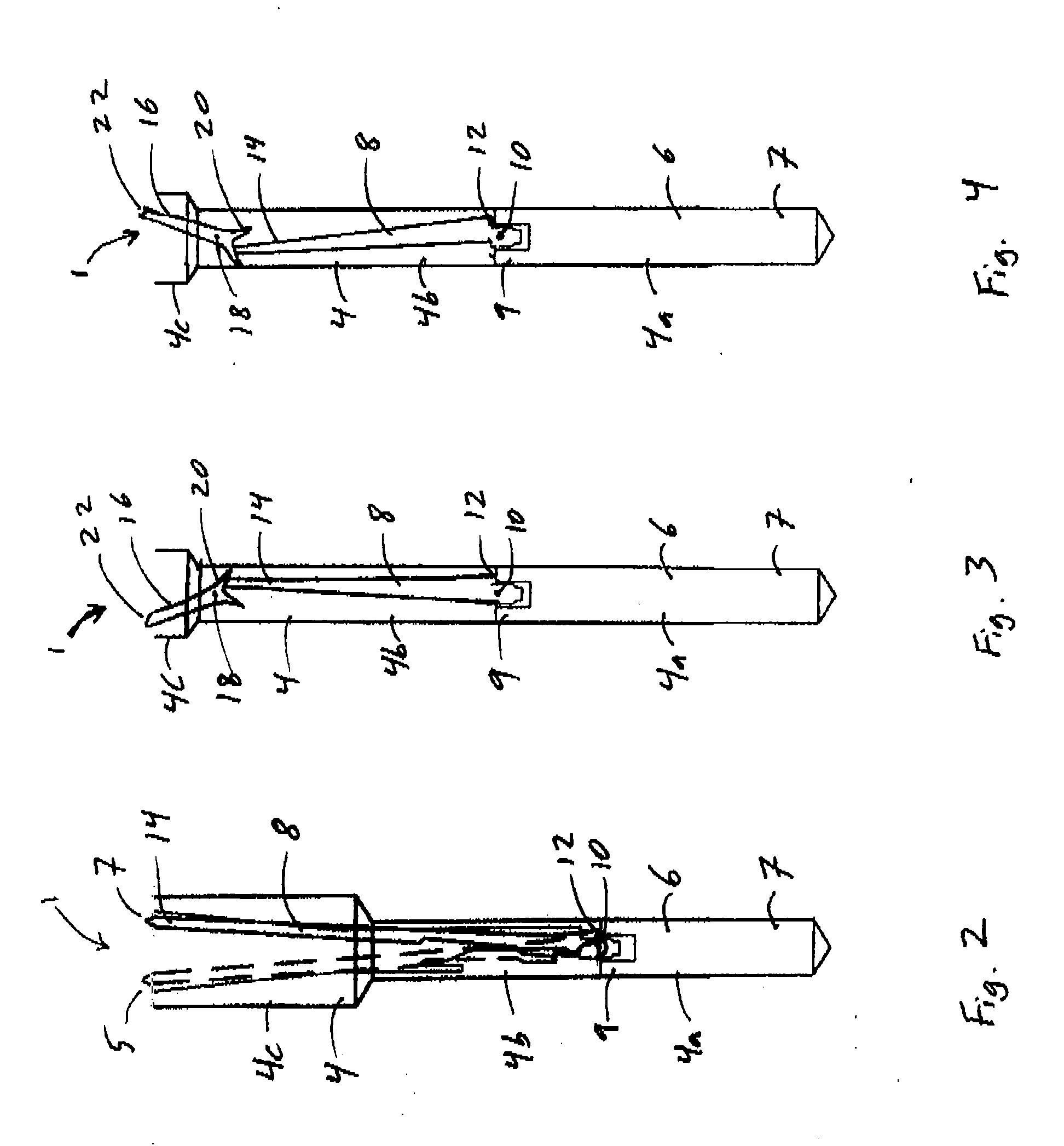
In many applications, achieving the proper fastener tightness (tension) and maintaining this tightness once the
system is placed in service is problematic.
Monitoring the load on a fastener during installation and service is equally problematic.
As the fastener is tightened, this load increases to a maximum
break point i.e. where the fastener yields, breaks, or its integrity is otherwise compromised.
The loss of tension that results from these occurrences can cause misalignment or premature wear in the
assembly, leakage (in applications where the fastener is used for sealing), or catastrophic joint failure due to excessively high loads on other members of the
assembly.
Because current fasteners do not reliably indicate the status of the tension in the fastener, users must often use cumbersome methods to check the tightness of each bolt, or simply retighten all of the fasteners regardless of whether such re-tightening is needed.
The re-torquing (i.e. tightening) of a fastener, however, induces wear and strain in the fastener
system from
corrosion, friction, variations in nut condition, torque values, and the like.
Thus, such visual load indicators are typically only available in larger fasteners or in fasteners having enlarged heads.
For example, electronic or ultrasonic methods for determining existing clamp load require experienced operators, expensive equipment, clean surfaces and records of pre-installation test values for each bolt or stud.
Moreover, devices that require complicated
electronics tend to add to the expense, maintenance and unreliability of the system.
In addition, such systems may be adversely affected by shock and other extreme conditions.
These systems generally require skilled labor to use complicated and sophisticated measurement techniques.
Additionally, the reference surfaces generally are exposed to the outside environment which often leads to outside forces affecting the system.
Determination of intermediate load levels, or partial loosening of a fastener, is not possible.
Furthermore, because most fasteners are in-service in an outdoor environment, variations in
sunlight may
restrict an inspector's ability to determine the specific color of the indicator.
While this device has some utility in certain applications, over time, the device can become inaccurate and lose calibration.
This loss of calibration has been found to be inherent in the design of the U-shaped sensing element, because as the element is continually strained, its calibration characteristics are inherently affected.
In addition, temperature may affect the bending characteristics of this U-shaped element.
Also, when attempting to match coefficients of linear expansion between the bolt and the U-shaped element, one is limited due to the fact that only a limited number of materials are sufficiently resilient to be used for this design.
The bottom of the U is in constant contact with the abutment and any shock will be transferred at the bottom of the U and tend to deform the U-shaped element causing it to lose calibration.
Due to the design of this system, and the complex arrangement of the levers, and position of the indicator window, the indicator components must be positioned on the outside of the bolt, which in some applications is not possible due to space restrictions.
In cases where it is possible to use such a configuration, the elements of the instrument may be susceptible to outside forces and damage.
Upon damage, no convenient method exists to verify whether or not the unit is still calibrated.
Thus, a need exists for a visual load indicator that may be used with smaller and more conventional fastener configurations in addition to overcoming the shortcomings of prior art apparatuses and methods that are
time consuming, skilled labor intensive, extend outside the fastener, subject to environmental conditions, unreliable, or inoperable at high temperatures and require expensive
measuring equipment.


