Method and device to determine the q factor for flow meters

a flow meter and q factor technology, applied in the direction of mass flow measurement devices, measurement devices, instruments, etc., can solve the problems that input values cannot be determined from measured oscillation courses at great expense, and achieve the effects of improving disclosure, improving accuracy, and improving accuracy

Inactive Publication Date: 2008-02-28
ABB PATENT GMBH
View PDF8 Cites 35 Cited by
  • Summary
  • Abstract
  • Description
  • Claims
  • Application Information

AI Technical Summary

Benefits of technology

[0010] The advantage of both alternative exemplary solutions can be that the computational steps which are expressed in them can easily be implemented by a device. For this purpose, the exemplary methods which are the subject of the disclosure can be embodied by a computer program product, which implements a routine to determine the Q factor by corresponding control commands which are held in software. This software can be capable of running on a microprocessor of an associated electronic device, with an exciter unit which can be attached to a meter tube of a flow meter to generate a uniform oscillating movement and a sensor unit to measure the oscillating movement, which influences the flow, of the meter tube, and the measured values of which are analyzed by an analysis unit, which is connected downstream, to determine the desired flow parameter and the Q factor, as specified by a stored computational algorithm.
[0011] According to another exemplary technique, which improves the disclosure, it is proposed that the analysis unit has a memory unit to store Q factors, which are each provided with time stamps. At the start of the lifetime of the flow meter, the initial Q factor can be stored in this memory unit, further Q factors with associated time stamps being additionally stored at defined subsequent time intervals during the lifetime of the flow mete

Problems solved by technology

However, these input values can only be determined fr

Method used


Image

  • Method and device to determine the q factor for flow meters
  • Method and device to determine the q factor for flow meters
  • Method and device to determine the q factor for flow meters

Examples


Embodiment Construction

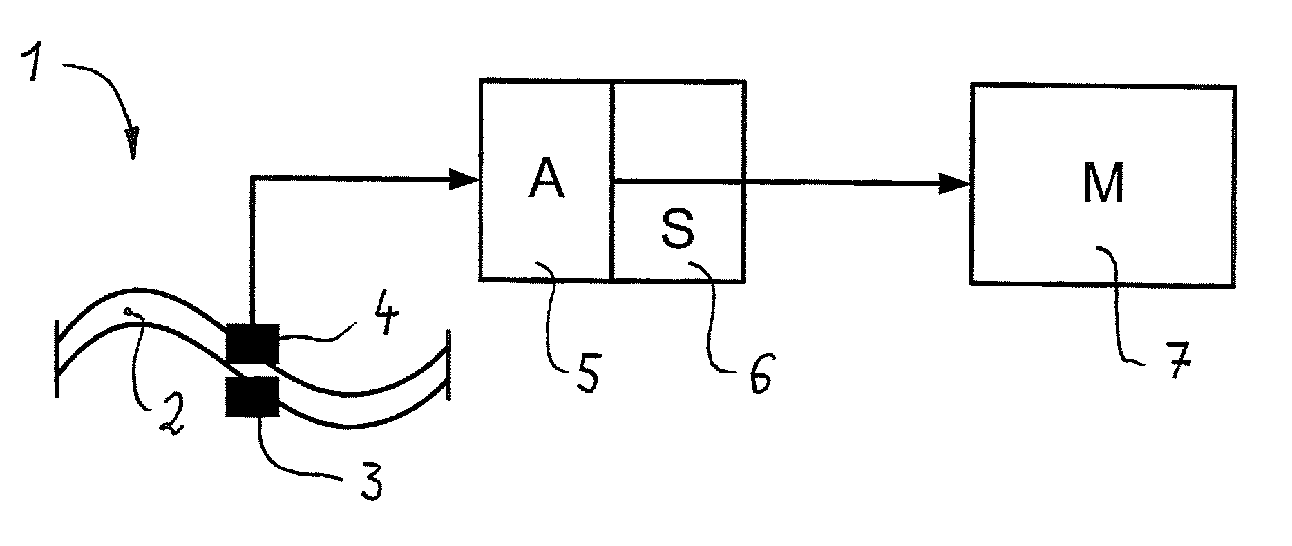
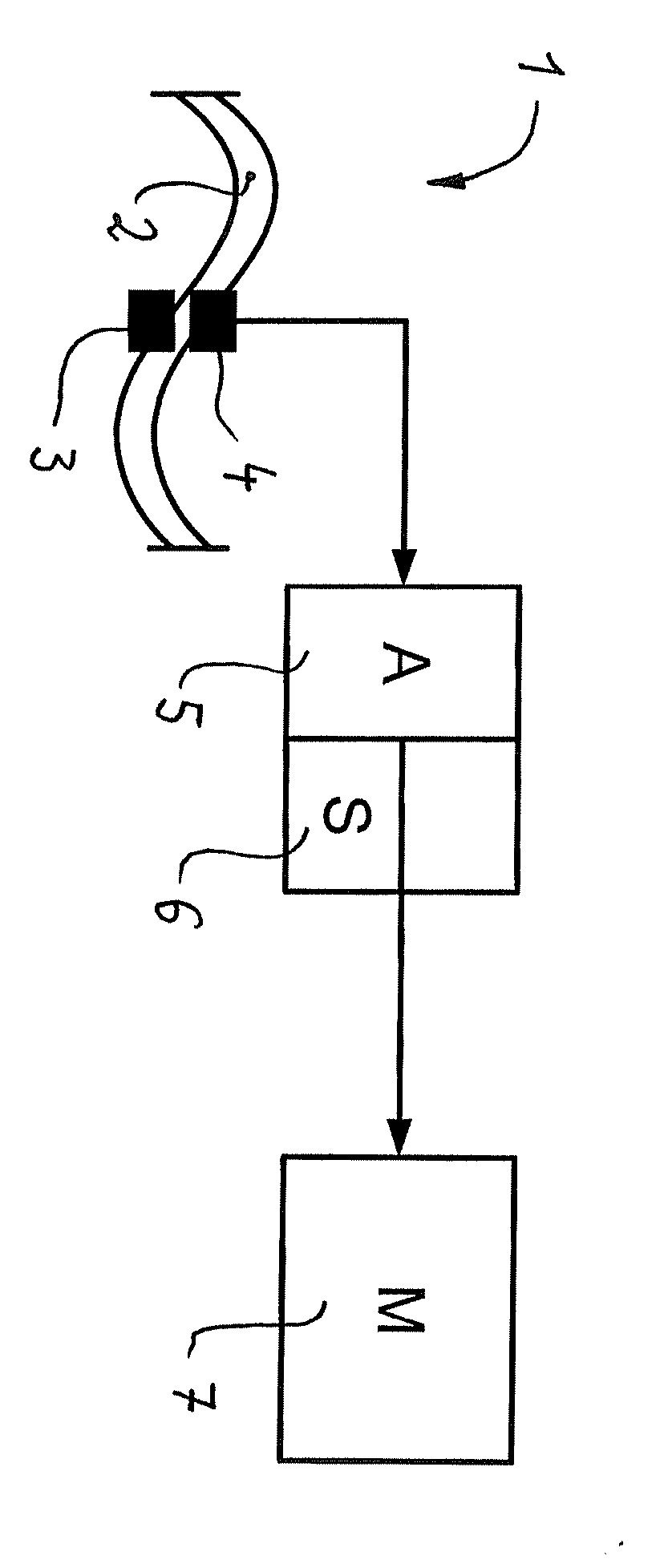
[0015] According to the FIGURE, an exemplary flow meter 1, e.g., a Coriolis flow meter, has a meter tube 2, through which a free-flowing measuring substance flows in a way which is known per se. The meter tube 2 is put into uniform oscillating movement, here sinusoidal oscillation, via an exciter unit 3. This uniform oscillating movement is influenced by the flow of the measuring medium within the meter tube 2, and the resulting oscillation signal is captured via a sensor unit 4 which is arranged on the meter tube 2, and which here, to achieve a high signal quality, is in the form of a median sensor relative to the meter tube 2. The oscillating movement of the meter tube 2, which is captured by the sensor unit 4, is made available on the input side to an electronic analysis unit 5, in the form of an electronic signal.

[0016] One purpose of the analysis unit 5 is to determine the desired flow parameter, here the mass flow of the flow medium through the meter tube 2.

[0017] The analys...


PUM


Abstract

Method and device to determine the Q factor for a flow meter, with an exciter unit which can be attached to a meter tube to generate a uniform oscillating movement and a sensor unit to measure the oscillating movement, which is influenced by the flow, of the meter tube, and the measured values of which are analyzed by an analysis unit, which is connected downstream, to determine the desired flow parameter and the Q factor, as specified by a stored computational algorithm.

Description

RELATED APPLICATIONS [0001] This application claims priority under 35 U.S.C. §119 to German Application 10 2006 039 726.6 filed in Germany on Aug. 24, 2006, the entire contents of which are hereby incorporated by reference in their entireties.TECHNICAL FIELD [0002] A method and a device to determine the Q factor is disclosed for a flow meter, e.g., a Coriolis flow meter, the meter tube of which, through which the measuring medium flows, is stimulated via at least one exciter unit which generates a uniform oscillation movement, and the oscillation movement of which, which is influenced by the flow, is captured via at least one sensor unit and then analyzed by an analysis unit to determine the desired flow parameter, the Q factor being additionally determined by calculation for diagnostic purposes. BACKGROUND INFORMATION [0003] The Q (quality) factor is a measure of specified properties of an oscillating system, and is mainly used in the electrical engineering field in relation to osc...

Claims


Application Information

Patent Timeline
IPC IPC(8): G01F1/84
CPCG01F1/8436G01F25/0007G01F1/849G01F25/10
Inventor KASSUBEK, FRANKPETRI, GUNTERGEBHARDT, JORGDEPPE, LOTHARFRIEDRICHS, RENEKELLER, STEFFEN
Owner ABB PATENT GMBH
Why Eureka
Try Eureka