Method and apparatus for cleaning tanks and other containers

a technology for cleaning tanks and other containers, applied in the direction of cleaning using liquids, special purpose vessels, transportation and packaging, etc., can solve the problems of limited tank capacity of boats and/or drilling rigs, oil-based and synthetic-based drilling fluids, harmful to personnel and the environment, etc., to improve cleaning performance and efficiency, reduce waste water volume, and reduce exposure of personnel

Inactive Publication Date: 2008-02-28
BALL DAVID M
View PDF11 Cites 26 Cited by
  • Summary
  • Abstract
  • Description
  • Claims
  • Application Information

AI Technical Summary

Benefits of technology

[0019]The cleaning apparatus of the present invention comprises at least one sprayer nozzle beneficially mounted within a tank to be cleaned. Although said at least one nozzle can be mounted within such tank using any number of different methods, in the preferred embodiment said at least one nozzle is mounted to an internal surface of such tank using adjustable mounting means. Such adjustable mounting means can include, but are not necessarily limited to, one or more magnetic mounting brackets. Use of said at least one sprayer nozzle eliminates the need for personnel to enter a tank for prolonged periods. Rather, such personnel are typically only required to enter a tank in order to install, reposition and / or remove said at least one sprayer nozzle in such tank.
[0021]Because high concentrations of barite and other deposited solids may be present on or near the base of a tank, said at least one sprayer nozzle can be oriented in a manner that would focus a spray pattern on the lower portion of tank. Use of adjustable mounting means, and / or sprayer nozzles that can be aimed, allow focused washing of certain portions of a tank (such as, for example, the base of a tank having a layer of deposited solids) in order to ensure effective cleaning of such tank. If desired, the aiming direction of said at least one spray nozzle can be controlled remotely by personnel located outside of a tank being cleaned. Additionally, the duration of spray time can also be focused for longer periods in certain portion(s) of a particular tank, if desired.
[0024]Recovered water and / or other wash fluids are directed from the segregated compartment(s) of the separator unit into the tank being cleaned via said at least one sprayer nozzle. In this manner, such water and / or wash fluid is recycled and reused as part of a “closed-loop” system, thereby reducing the amount of water and / or wash fluids needed (as well as effluent that must transported to an off-site facility for disposal).
[0025]In the preferred embodiment, at least one chemical agent or other beneficial additive can be added to the water or other washing fluid to be sprayed within a tank to be cleaned. Such chemical agent(s) promote solids dropping out of suspension, thereby allowing solids and liquids to more readily separate within the separator unit, which in turn improves the overall performance of said separator unit.
[0028]There are many advantages associated with the present invention including, but necessarily limited to: (1) improved cleaning performance and efficiency by at least 50% as compared to conventional manual cleaning methods; (2) reduced exposure of personnel to the inside of tanks being cleaned (as well as substances contained therein) by at least 80% compared to conventional manual cleaning methods; (3) reduction in waste water volumes generated as compared to conventional fluid chemical additives; (4) ease of handling of waste materials; and (5) ability to gauge cleaning progress in real time.

Problems solved by technology

Many of these additives, as well as oil-based and synthetic-based drilling fluids, can be harmful to personnel and the environment.
In such cases, the limited tank capacity of boats and / or drilling rigs necessitates using the same tanks to store such different drilling fluids.
However, because such different types of drilling fluids may not be compatible with one another, it is frequently necessary to clean such tanks before switching the fluids to be stored in such tanks.
The process of cleaning tanks can often prove to be difficult, expensive and time consuming.
Such cleaning can be especially challenging when solids are permitted to drop out of suspension.
This method of cleaning tanks can be very physically challenging, especially on hot days when temperatures inside the tanks can be extremely high (and ventilation within such tanks can be very poor).
Further, this method of cleaning tanks raises safety concerns, because personnel inside the tanks are frequently exposed to drilling fluid residue, toxins and / or contaminants that may be present within such tanks.
However, performance of such prior art cleaning devices has proven to be less than satisfactory, often because such prior art cleaning devices cannot adequately reach all areas of tanks to be cleaned and, further, most chemical compounds used with in connection with prior art automated cleaning devices are ineffective at removing solids from tanks being cleaned.
Moreover, said prior art devices can be cumbersome, as well as difficult and expensive to operate.
After being used, the wash water effluent or other fluid typically contains significant amounts of solids or other contaminants.
As a result, such effluent typically cannot be dumped or otherwise disposed of where the tank is located due to environmental concerns.
While this solution can be generally functional, it is not without significant problems.
One major problem associated with the off-site disposal of wash water effluent is increased cost.
Such added equipment and labor increases the costs associated with the tank cleaning process.
Another major problem associated with off-site disposal of wash water or other effluent is the use of valuable rig space.
In most instances, storage boxes takes up a great deal of a rig's available work area.
This additional equipment can present logistical and / or safety problems on many boats and rigs.
Another problem associated with off-site disposal of waste water or other effluent wash fluid is environmental impact.
Such off-site disposal does not necessarily guarantee an overall reduction or elimination of environmental contamination.
As a result, the overall impact on the environment as a result of such offsite disposal can be significant.

Method used


Image

  • Method and apparatus for cleaning tanks and other containers
  • Method and apparatus for cleaning tanks and other containers
  • Method and apparatus for cleaning tanks and other containers

Examples


Embodiment Construction

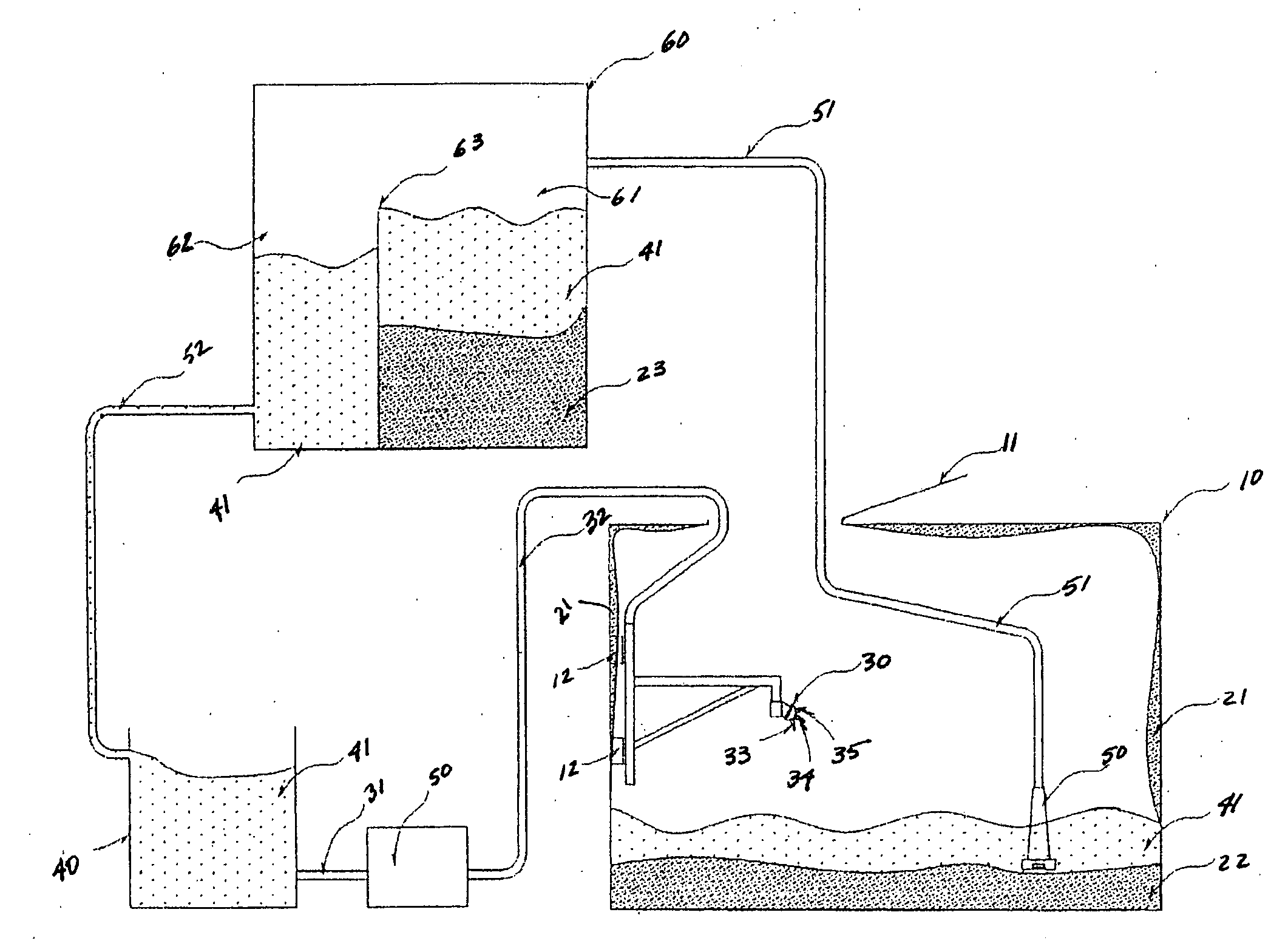
[0035]Referring to the drawings, FIG. 1 depicts a schematic view of the cleaning apparatus of the present invention. Tank 10, having access hatch 11, represents a storage tank to be cleaned. Although the present invention can be used to clean any number of tanks having different sizes, shapes and / or configurations, and containing any number of different fluids, tank 10 is described herein as a storage tank for drilling fluids and / or other solids-laden fluids, such as may be routinely encountered on boats and / or drilling rigs. Tank 10 contains drilling fluid residue 21 on certain internal surfaces of tank 10, as well as hardened solids 22 deposited at or near the bottom of tank 10. However, such description is for illustration only and is not intended to limit the scope of the present invention to a particular application or type of tank / enclosure to be cleaned.

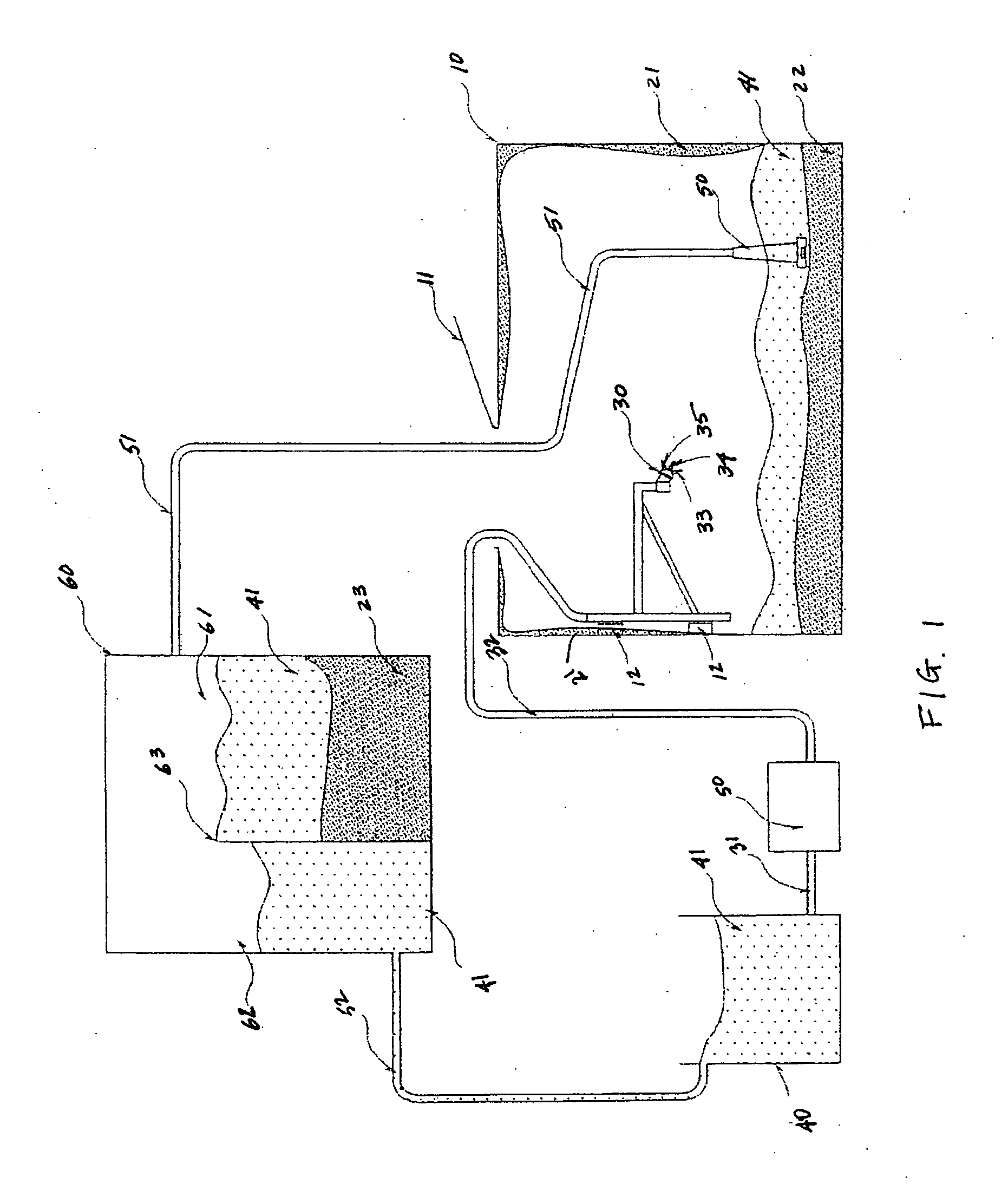
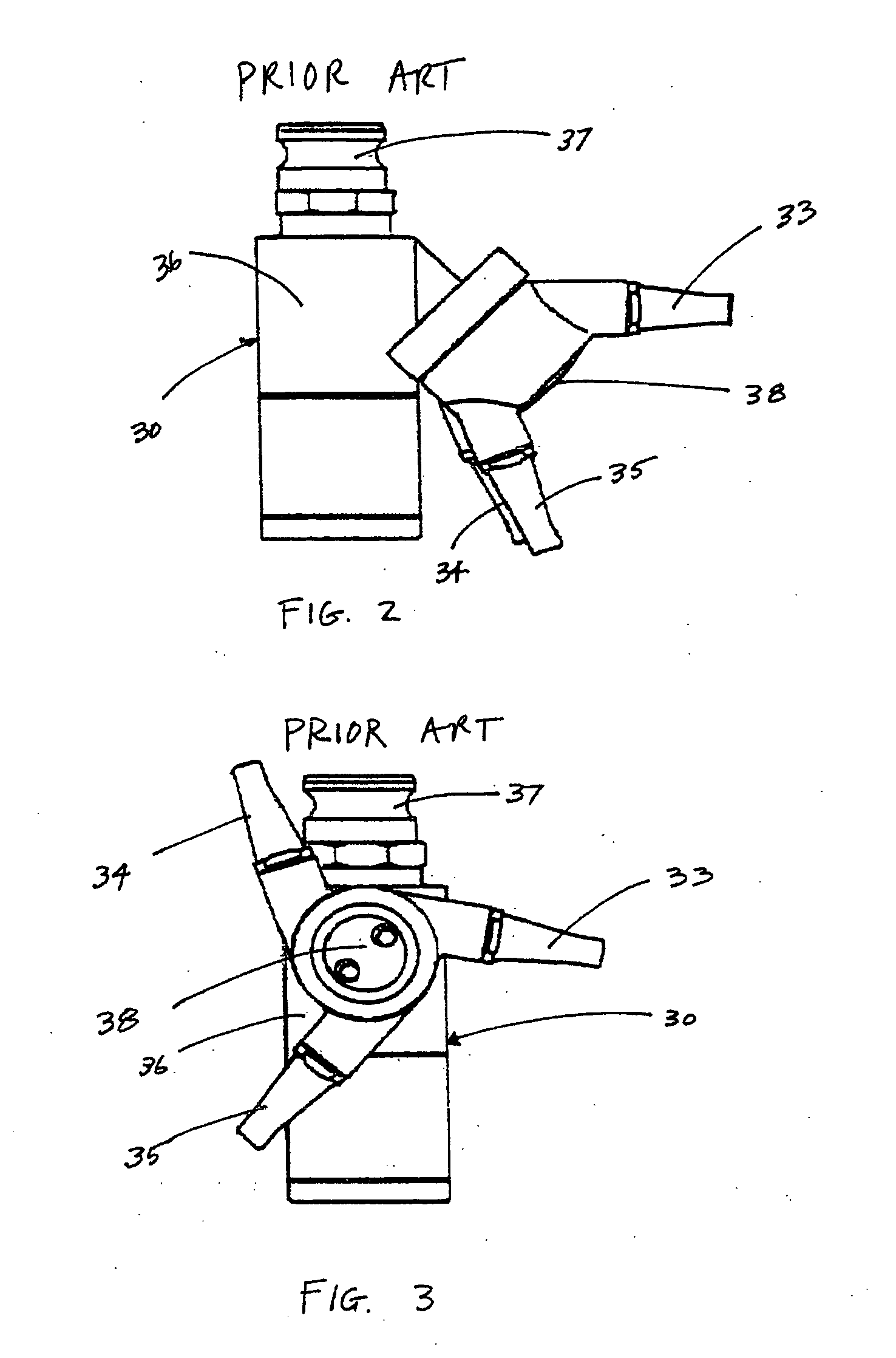
[0036]The cleaning apparatus of the present invention comprises at least one sprayer device 30 beneficially mounted within ...


PUM


Abstract

A closed-loop system for cleaning tanks and other enclosures utilizing adjustably mounted nozzles for spraying water, other wash fluid and / or beneficial chemical additive within the tanks or other enclosures to be cleaned. Effluent wash fluid leaving a tank is directed to a separator unit for separation of liquids and solids. Solids are disposed of or otherwise removed, while recovered liquids are directed for re-use. Exposure of personnel to the inside of such tanks or other enclosures to be cleaned is minimal.

Description

CROSS REFERENCES TO RELATED APPLICATIONS [0001]NoneFEDERALLY SPONSORED RESEARCH [0002]Not ApplicableSEQUENCE LISTING OF PROGRAM [0003]Not ApplicableBACKGROUND OF INVENTION[0004]1. Field of Invention[0005]The present invention pertains to a method and apparatus for cleaning tanks and other containers including, but not necessarily limited to, storage tanks on drilling rigs and marine vessels. More particularly, the present invention pertains to a method and apparatus for cleaning tanks, including the interior surfaces of such tanks, containing solids-laden fluids such as drilling muds and the like.[0006]2. Description of Related Art[0007]Tanks, containers and other similar enclosures are commonly used to store liquids in any number of different applications. Tanks of varying sizes and shapes are frequently used to store liquids in connection with numerous industries including, but not necessarily limited to, the oil and gas industry. Such tanks are especially prevalent in the offshor...

Claims


Application Information

Patent Timeline
Patent Type & Authority Applications(United States)
IPC IPC(8): B08B9/00B08B3/00B08B3/12
CPCB08B9/08B63B57/02B08B9/0936B08B9/0933
Inventor BALL, DAVID M.
Owner BALL DAVID M
Why Eureka
Try Eureka