Electromagnetic split flapper pressure relief valve

a split flapper and pressure relief valve technology, applied in fluid pressure control, process and machine control, instruments, etc., can solve the problems of large, expensive, difficult to package, and large, and achieve the effect of small, inexpensive, and easy to packag

Inactive Publication Date: 2008-02-28
HONEYWELL INT INC
View PDF15 Cites 8 Cited by
  • Summary
  • Abstract
  • Description
  • Claims
  • Application Information

AI Technical Summary

Benefits of technology

[0005]The present invention provides relatively small, inexpensive, and easy to package pressure relief and reverse flow protection valve. In one embodiment, and by way of example only, a pressure relief check valve system includes a valve body, a flapper, a magnet, an electromagnet, and a pressure sensor circuit. The valve body has an upstream side, a downstream side, and a flow channel that extends between the upstream and downstream sides. The flapper is rotationally mounted on the valve body and is movable between a closed position, in which the flapper at least substantially seals the flow channel, and an open position, in which the flapper unseals the flow channel. The magnet is coupled to the flapper. The electromagnet is coupled to the valve body and is configured to selectively receive electrical current. The electromagnet is operable, upon receipt of the electrical current, to either magnetically attract or not magnetically attract the magnet, to thereby at least substantially inhibit flapper rotation from the closed position or allow flapper rotation to the open position, respectively. The pressure sensor circuit is adapted to sense fluid pressure and is operable, based on the sensed fluid pressure, to selectively supply or interrupt the electrical current to the electromagnet.

Problems solved by technology

These valves, while generally safe, reliable, and robust, are in many instances relatively large, relatively heavy, relatively costly, and relatively difficult to package.
Moreover, typical pneumatic relief valves, while also generally safe, reliable, and robust, are typically implemented with relatively large sense areas to meet desired relief and flow specifications, making these relatively large, costly, and difficult to package, as well.

Method used


Image

  • Electromagnetic split flapper pressure relief valve
  • Electromagnetic split flapper pressure relief valve
  • Electromagnetic split flapper pressure relief valve

Examples


Embodiment Construction

[0011]The following detailed description of the invention is merely exemplary in nature and is not intended to limit the invention or the application and uses of the invention. Furthermore, there is no intention to be bound by any theory presented in the preceding background or the following detailed description. In this regard, although the invention is described herein as being implemented in an aircraft environmental control system, and more specifically as a filter bypass pressure relief valve, it will be appreciated that it could also be implemented in any one of numerous other locations in an aircraft environmental control system, and in any one of numerous other types of systems that direct the flow of various types of fluid, both within or apart from an aircraft.

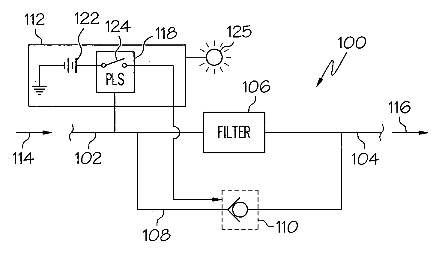
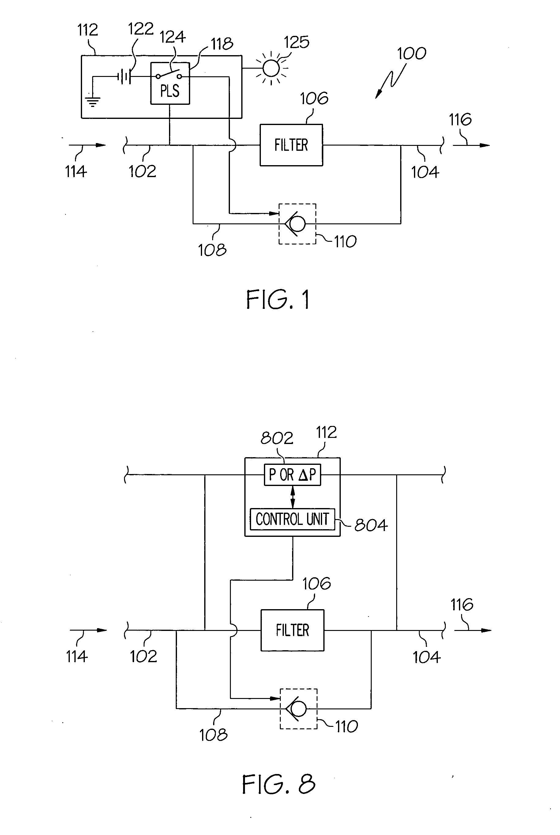
[0012]Turning now to FIG. 1, a simplified schematic diagram of a portion of an exemplary aircraft environmental control system 100 is depicted. The depicted portion of the environmental control system 100 includes an...


PUM


Abstract

A pressure relief check valve system includes a valve body, a flapper, a magnet, an electromagnet, and a pressure sensor circuit. The flapper is rotationally mounted on the valve body and is movable between a closed position and an open position. The magnet is coupled to the flapper, and the electromagnet is coupled to the valve body. The pressure sensor circuit is adapted to sense one or more fluid pressures and is operable, based on the one or more sensed fluid pressures, to selectively supply or interrupt the electrical current to the electromagnet. The electromagnet is coupled to receive the electrical current and, upon receipt of the electrical current, either magnetically attracts or does not magnetically attract the magnet, to thereby hold the flapper in the closed position or allow flapper rotation to the open position, respectively.

Description

TECHNICAL FIELD[0001]The present invention relates generally to a pressure relief valve and, more particularly, to an electromagnetically controlled pressure relief check valve.BACKGROUND[0002]Pressure relief valves are used in myriad systems and, as is generally known, are used to selectively relieve fluid pressure in a system or component of a system, if the fluid pressure therein attains a predetermined pressure value. One particular system that may include one or more pressure relief valves is an aircraft environmental control system (ECS). Aircraft ECSs typically include relatively low-pressure distribution ducts and, as such, may additionally include high-flow pressure relief and reverse flow pressure protection devices.[0003]In order to provide the desired relief and reverse flow protection functionalities, some ECSs include an electro-pneumatic relief valve. These valves, while generally safe, reliable, and robust, are in many instances relatively large, relatively heavy, re...

Claims


Application Information

Patent Timeline
Patent Type & Authority Applications(United States)
IPC IPC(8): G05D11/13G05D11/00
CPCG05D16/2013F16K31/082F16K15/038F16K31/084Y10T137/264Y10T137/7761Y10T137/7839Y10T137/7898Y10T137/87362Y10T137/87507
Inventor DENIKE, STUART K.MCGONIGLE, G. STEPHENSLEEPER, ROBERT D.DORSTE, CRAIG T.ATKINS, DON J.JIRA, JOSEPH J.
Owner HONEYWELL INT INC
Why Eureka
Try Eureka