Configurable Microfluidic Substrate Assembly

a microfluidic substrate and configuration technology, applied in the field of microfluidic substrate assemblies, can solve the problems of insufficient retooling of changes in specific applications, inability to meet the needs of industry, and inability to meet the needs of the industry, and achieve good design flexibility

Inactive Publication Date: 2008-02-28
PROTASIS CORP
View PDF12 Cites 169 Cited by
  • Summary
  • Abstract
  • Description
  • Claims
  • Application Information

AI Technical Summary

Benefits of technology

[0006]In certain preferred embodiments, at least some of the sockets configured to receive operative components are in fluid and / or electrical (e.g., electrical power, data, etc.) communications with each other via suitable flow channels or electrically conductive pathways in the substrate. For good design flexibility, as well be further understood from the detailed description below, it is generally preferred that all of the sockets adapted to receive an operative component are in fluid communication and electrical communication with each other.

Problems solved by technology

Additionally, the channels may contain fragile or environmentally sensitive structures, such as materials, architecture and / or devices used for analyzing the fluids or components contained therein.
Currently known miniaturized fluid-handling devices have not met all of the needs of industry.
A change in the specific application typically requires significant retooling and consequent additional costs.
Additionally, if a technician in the field realizes the need for additional functionality or essential features after production, the already produced devices are no longer useful and must be replaced.
So, not only are there costs incurred with redesign, retooling, and additional manufacturing, but there can also be a loss of time and money already spent on the previously, produced substrates.

Method used


Image

  • Configurable Microfluidic Substrate Assembly
  • Configurable Microfluidic Substrate Assembly
  • Configurable Microfluidic Substrate Assembly

Examples


Embodiment Construction

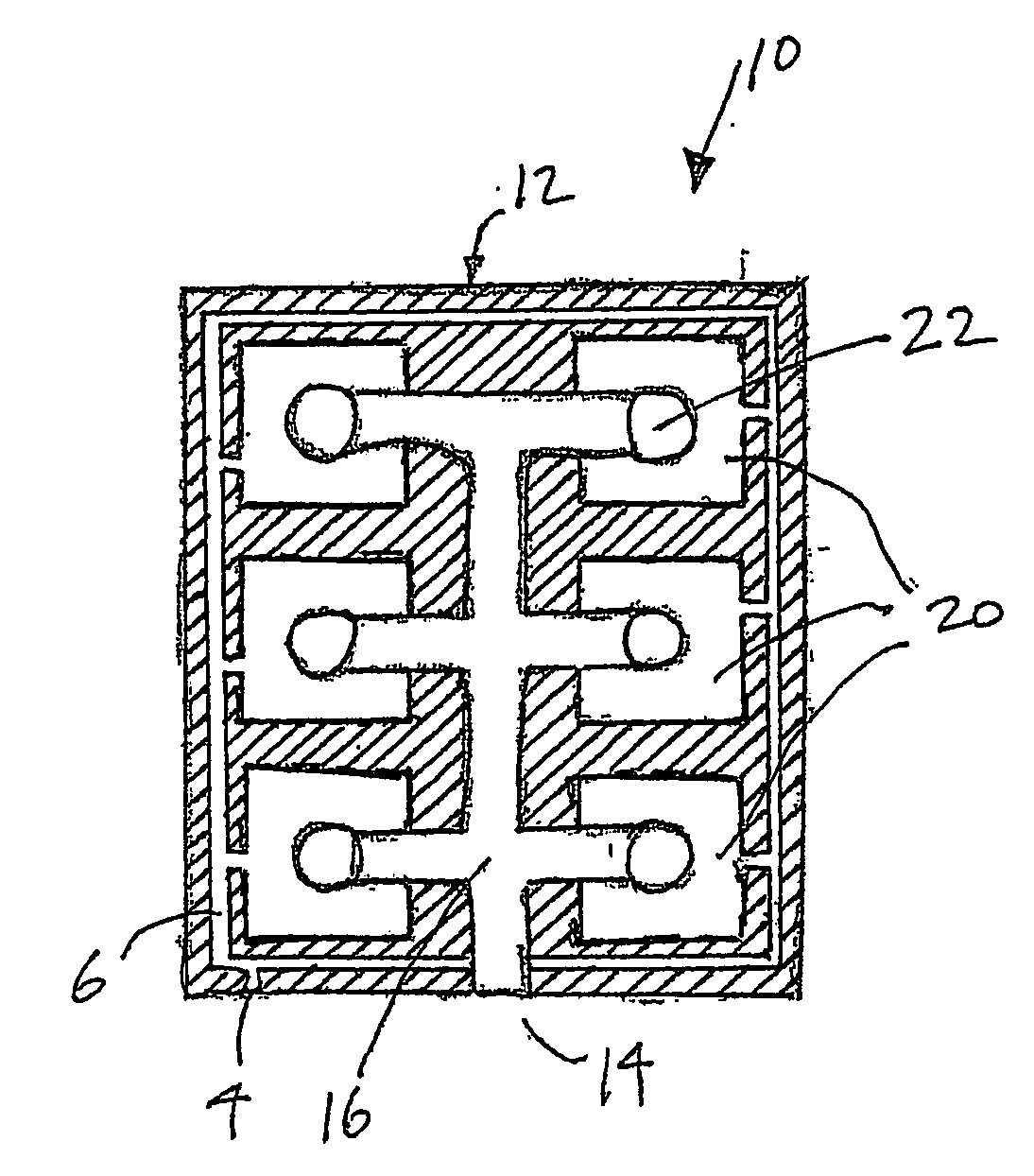
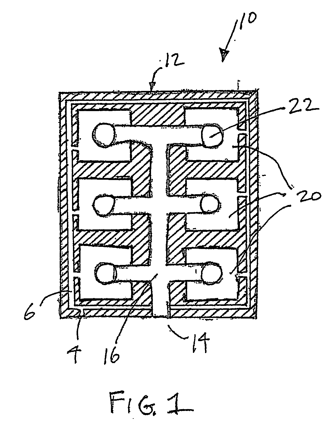
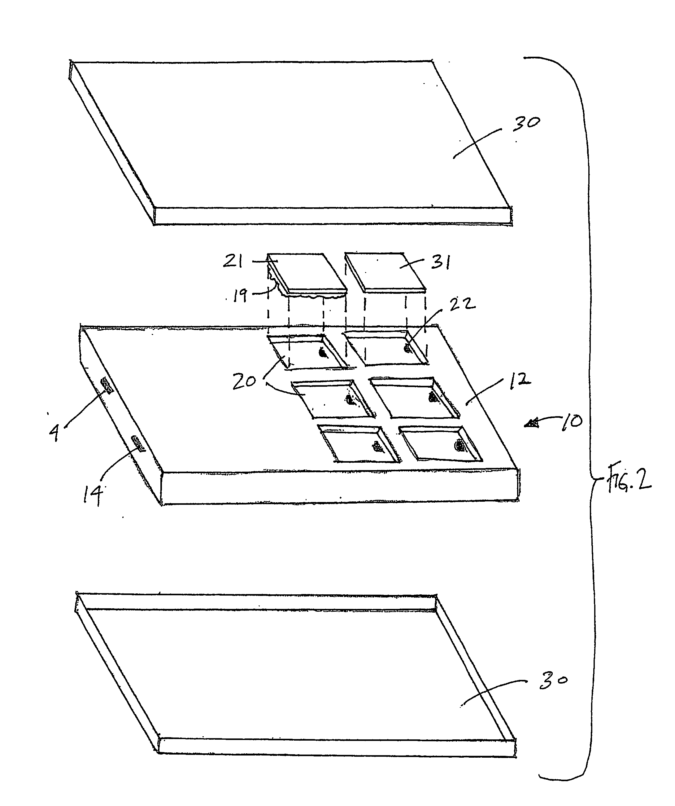
[0028]Numerous embodiments of the present invention are possible and will be apparent to those skilled in the art, given the benefit of this disclosure. The detailed description provided herein, for convenience, will focus on certain illustrative and exemplary embodiments.

[0029]Preferred embodiments of the devices disclosed herein can be utilized, for example, in any of a wide range of automated tests for the analysis and / or testing of a fluid. As used here, the term “fluid” refers to gases, liquids, supercritical fluids and the like, optionally containing dissolved species, solvated species and / or particulate matter. Testing or analysis of a fluid, as used herein, has a broad meaning, including any detection, measurement or other determination of the presence of a fluid or of a characteristic or property of the fluid or of a component of the fluid, such as particles, dissolved salts or other solutes or other species in the fluid. Especially preferred embodiments of fluid handling d...


PUM

PropertyMeasurementUnit
pressureaaaaaaaaaa
fluid flow ratesaaaaaaaaaa

Abstract

A microfluidic substrate assembly includes a substrate body having at least one fluid inlet port. At least one microscale fluid flow channel in the substrate is in fluid communication with the inlet port for transport of a fluid to be tested. The substrate body also has a plurality of sockets, with each of one or sockets configured to receive an operative component. At least one socket is in communication with the microscale fluid flow channel.

Description

FIELD OF THE INVENTION[0001]The present invention relates to fluid-handling substrate devices and, more particularly, to microfluidic substrate assemblies and to methods for making certain preferred embodiments of microfluidic substrate assemblies.BACKGROUND[0002]Systems for biochemical, chemical, and molecular analysis can be miniaturized as substrates with multifunctional capabilities including, for example, chemical, optical, fluidic, electronic, acoustic, and / or mechanical functionality. Miniaturization of these systems offers several advantages, including increased portability and lower production cost. Such devices can be fabricated from a diverse ensemble of materials including, for example, plastics or polymers, metals, silicon, ceramics, paper, and composites of these and other materials. Typically, such substrates include fluid channels extending within them for the transport and / or analysis of fluids or components contained in the fluids. Additionally, the channels may co...

Claims


Application Information

Patent Timeline
Patent Type & Authority Applications(United States)
IPC IPC(8): B01D57/02B01J19/00G01N25/20G01N27/00B01L3/00G01N30/60
CPCB01J2219/00783B01J2219/00804B01J2219/0081B01L3/502715B01L2200/027B01L2200/028G01N30/6095B01L2200/10B01L2300/023B01L2300/024B01L2300/0816B01L2300/0887G01N30/6047B01L2200/04
Inventor STRAND, DAVIDBARROW, DAVID
Owner PROTASIS CORP
Why Eureka
Try Eureka