Light directing laminate

a technology of light directing and laminates, applied in the field of light directing films, can solve the problems of unsatisfactory bright spots, reduced gain, streaks,

Inactive Publication Date: 2008-02-28
3M INNOVATIVE PROPERTIES CO
View PDF14 Cites 42 Cited by
  • Summary
  • Abstract
  • Description
  • Claims
  • Application Information

AI Technical Summary

Benefits of technology

[0043]An advantage of the present invention is improved adhesion because of full face adhesion between adjacent films. Another advantage of the invention is that distance D is chosen so that the visibility of a wet out pattern is reduced or eliminated. Furthermore, D is selected so that any optical coupling between the two films due to adhesive layer 46 results in little or no reduction in gain.

Problems solved by technology

Contact between the two films can result in visibly apparent and undesirable bright spots, streaks, or lines, often referred to as “wet out.” Wet out can also reduce gain.

Method used


Image

  • Light directing laminate
  • Light directing laminate
  • Light directing laminate

Examples


Embodiment Construction

[0020]The present invention is applicable to displays, such as liquid crystal displays (LCDs), and is believed to be particularly useful for hand-held LCD devices where it is desirable for the device to be thin, have high gain, and have a display area free of visible defects.

[0021]In the specification, a same reference numeral used in multiple figures refers to the same or similar elements having the same or similar properties and functionalities.

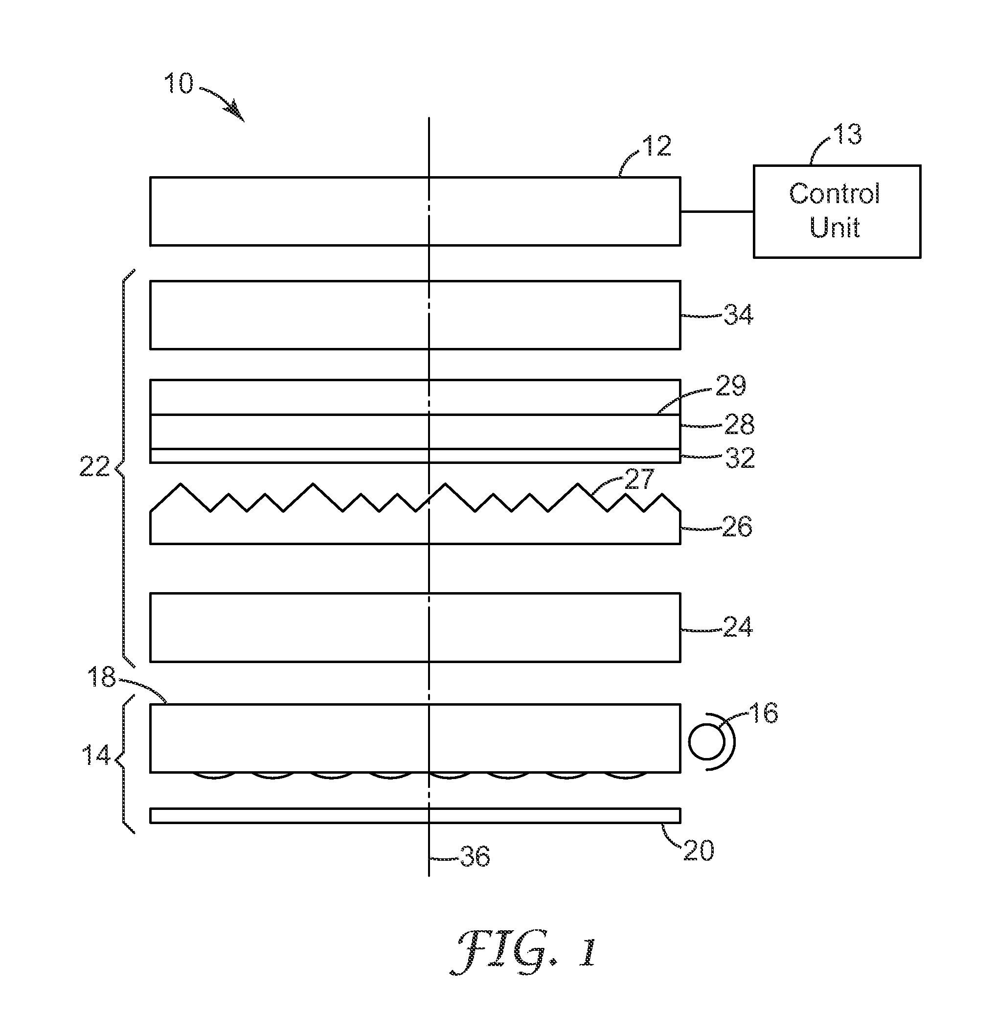
[0022]FIG. 1 is a schematic side-view of a display system 10. Display system 10 includes an electronic display unit 12, a control unit 13, a film stack 22, and a back light assembly 14 which includes a light source 16, a light guide 18, and a reflector layer(s) 20.

[0023]Display unit 12 could be a liquid crystal display (LCD) panel, which is typically sandwiched between two glass layers. Display unit 12 may include absorbing polarizers above and below the LCD panel to provide polarization contrast typically required for producing a polarizat...


PUM


Abstract

A light management film package includes a first optical film having a structured surface and a second major surface, a second optical film having a first major surface and a second major surface disposed adjacent to and making contact with the structured surface of the first optical film via an adhesive layer. The structured surface of the first optical film includes a plurality of tall structures separated by short structures with the tops of neighboring tall structures separated by a distance of between about 50 and about 150 microns. The tall structures of the first optical film penetrate the adhesive layer, but the short structures do not.

Description

BACKGROUND OF THE INVENTION[0001]The present invention relates to light directing films for optical displays. More particularly, the present invention relates to a light directing film having a structured surface with tall structures separated by short structures such that a distance between neighboring tall structures is in a specific range to maximize gain and minimize visible wet out.[0002]Optical displays, such as liquid crystal displays (LCDs) are becoming increasingly commonplace, finding use, for example, in cellular phones, hand-held computer devices ranging from personal digital assistants (PDAs) to electronic games, to larger devices such as laptop computers, and LCD monitors and television screens. Light directing films are used to increase the luminance of light exiting an optical display in a preferred direction, typically normal, or “on-axis”, to the surface of the display.[0003]The 3M brand Brightness Enhancement Film (BEF) from Minnesota Mining and Manufacturing (3M)...

Claims


Application Information

Patent Timeline
Patent Type & Authority Applications(United States)
IPC IPC(8): G02B5/02
CPCG02F1/133606G02F1/1335
Inventor TOLBERT, WILLIAM A.NELSON, JAMES M.ISBERG, THOMAS A.HIGHTOWER, ANDREW L.FAKLIS, DEAN
Owner 3M INNOVATIVE PROPERTIES CO
Why Eureka
Try Eureka