Mobile communication system using receiving apparatus and power supply control method

a technology of receiving apparatus and power supply control, which is applied in the direction of current supply arrangement, power management, sustainable buildings, etc., can solve the problems of increasing power consumption, inability to reduce power consumption by reducing the number of finger circuits, and large power consumption of these circuits, so as to achieve further reduction of power consumption and power consumption. the effect of reducing power consumption

Inactive Publication Date: 2008-02-28
RENESAS ELECTRONICS CORP
View PDF7 Cites 18 Cited by
  • Summary
  • Abstract
  • Description
  • Claims
  • Application Information

AI Technical Summary

Benefits of technology

[0014]In a receiving apparatus, a mobile communication system, and a receiving method according to the present invention, the power consumption can be reduced. When a state of reception on a propagation path is favorable, the power consumption can be further reduced. Thus, the power consumption can be controlled in accordance with the state of reception on the propagation path.

Problems solved by technology

The finger circuits, rake combining section, and error correcting circuit have complicated configurations and are large-scale circuits.
Therefore, power consumption of these circuits is very large.
For this reason, the power consumption increases.
Therefore, reduction of the power consumption by reducing the number of finger circuits is not practicable because the reception sensitivity is deteriorated.
However, in these related arts, an error correcting circuit always operates even in the good reception state, resulting in large power consumption.

Method used


Image

  • Mobile communication system using receiving apparatus and power supply control method
  • Mobile communication system using receiving apparatus and power supply control method
  • Mobile communication system using receiving apparatus and power supply control method

Examples


first embodiment

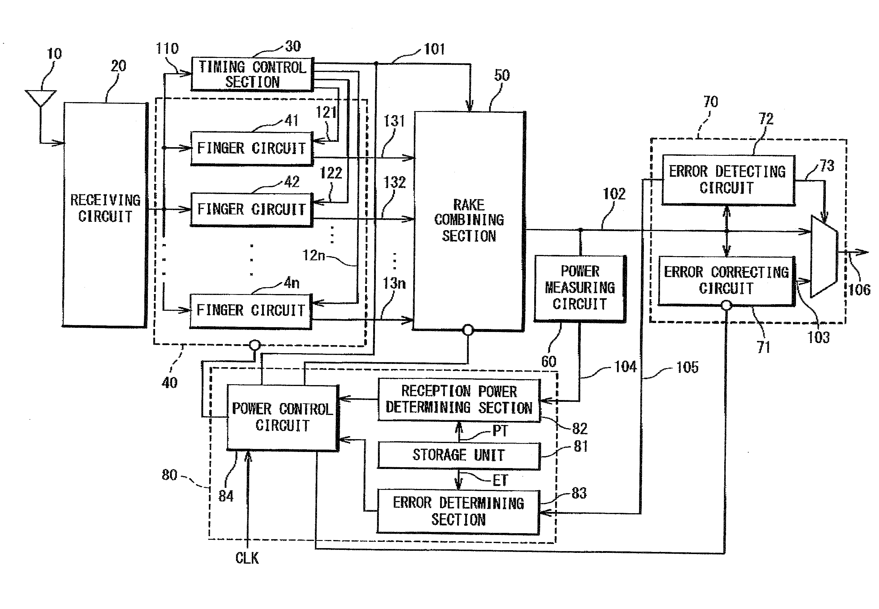
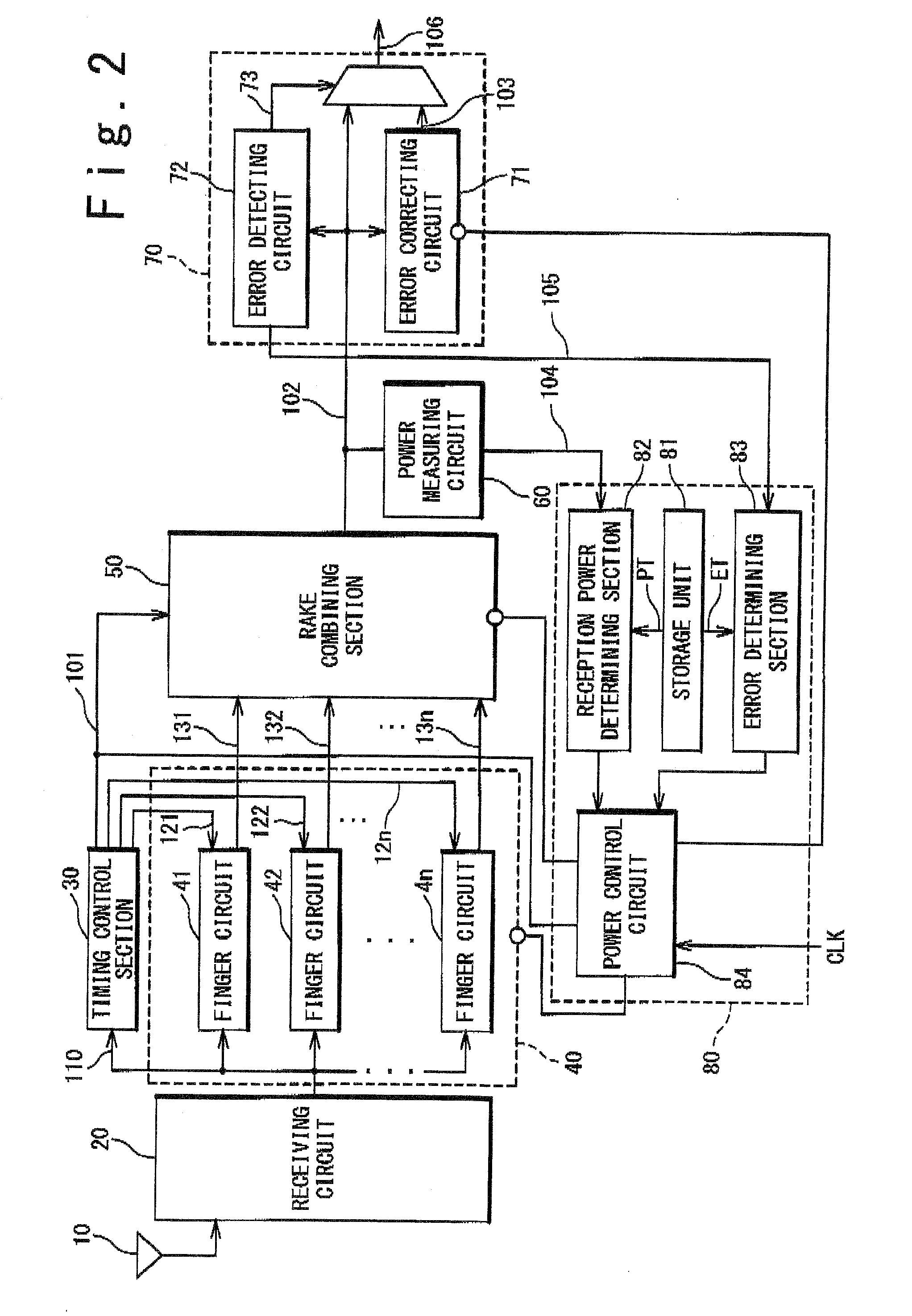
[0028]The multi-path signal received by the mobile phone terminal 1 is subjected to a despreading process, a rake combining process, and an error correcting process by a receiving apparatus shown in FIG. 2, and then subjected to a decoding process by a decoder (not shown). Hereinafter, detailed configuration of the receiving apparatus according to the present invention will be described with reference to FIGS. 1 to 4.

[0029]Referring to FIG. 2, the receiving apparatus according to the present invention includes an antenna 10, a receiving circuit 20, a timing control section 30, a rake finger section 40; a rake combining section 50, a power measuring circuit 60, an error control section 70, and a power supply control section 80.

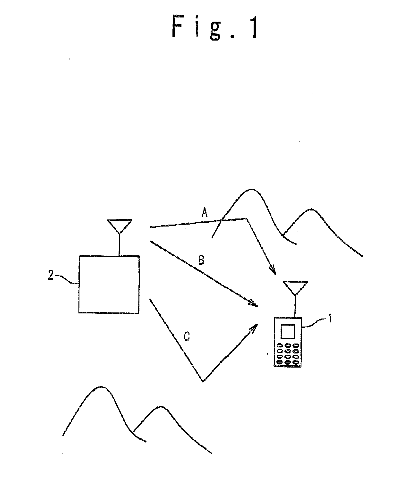
[0030]The antenna 10 receives a multi-path signal from the base station 2 and transmits it to the receiving circuit 20. The receiving circuit 20 down-converts the multi-path signal received by the antenna into an IF signal and then quadrature-demodulates the si...

second embodiment

[0063]As described above, the receiving apparatus can selectively use the finger circuits, the rake combining section 50, and the error correcting circuit 71 in a stepwise manner by determination through comparison of a plurality of power conditions of the combined reception data 102 combined in the rake combining section 50. Thus, the number of finger circuits executing the despreading process and the error correction processing can be changed based on the reception level and the error rate, which permits expecting an improvement in the power consumption and the receiving sensitivity in accordance with a reception state. That is, the receiving apparatus according to the present embodiment can change, in a stepwise manner in accordance with a reception state, between the mode putting a priority on reduction in the power consumption and the mode putting a priority on an improvement in the receiving sensitivity.

[0064]The embodiments of the present invention have been described above,...


PUM


Abstract

A receiving apparatus includes an error detecting circuit configured to detect an error of a reception signal; an error correcting circuit configured to correct the detected error of the reception signal; a power measuring circuit configured to measure a power value of the reception signal; and a power supply control section configured to control a power supply to the error correcting circuit based on the power value. The receiving apparatus further includes a receiving circuit configured to receive a radio signal; a rake finger section configured to execute a despreading process on the signal received by the receiving circuit, and a rake combining section configured to carry out a rake combination of the plurality of signals subjected to the despreading process to generate the reception signal.

Description

TECHNICAL FIELD[0001]The present invention relates to a mobile communication system.BACKGROUND ART[0002]A mobile communication system of a spread spectrum system (for example, CDMA (Code Division Multiple Access) system) is known which employs a technique (rake reception) of receiving a plurality of incoming radio waves and improving a receiving sensitivity through rake combination. Specifically, a plurality of radio waves are delayed and superposed due to multi-path propagation path and then are subjected to a despreading process by a plurality of finger circuits, and supplied to a rake combining section. The rake combining section combines signals separated through despreading processes for respective paths, with respect to time and phase. At this time, the rake combining section combines the signals through a maximum ratio combining in which the separated signals are weighted based on the S / N ratios of the respective paths. The combined reception signal is subjected to error corr...

Claims


Application Information

Patent Timeline
Patent Type & Authority Applications(United States)
IPC IPC(8): H04B1/707H04B1/16H04M1/73H04W28/04H04W52/02H04W76/02
CPCH04B1/7115Y02B60/50H04L1/0053
Inventor NAKAJIMA, AKIRA
Owner RENESAS ELECTRONICS CORP
Why Eureka
Try Eureka