Hollow core floor and deck element

a technology of hollow core and floor, applied in the direction of bridges, bridge structural details, ceilings, etc., can solve the problem of inhibiting the use of hollow core panels

Inactive Publication Date: 2008-03-06
MARSCHKE CARL R
View PDF56 Cites 1 Cited by
  • Summary
  • Abstract
  • Description
  • Claims
  • Application Information

AI Technical Summary

Problems solved by technology

However, the use of such hollow core panels has been inhibited because of difficulties in fabricating the panels in an efficient and cost effective manner.

Method used


Image

  • Hollow core floor and deck element
  • Hollow core floor and deck element
  • Hollow core floor and deck element

Examples


Embodiment Construction

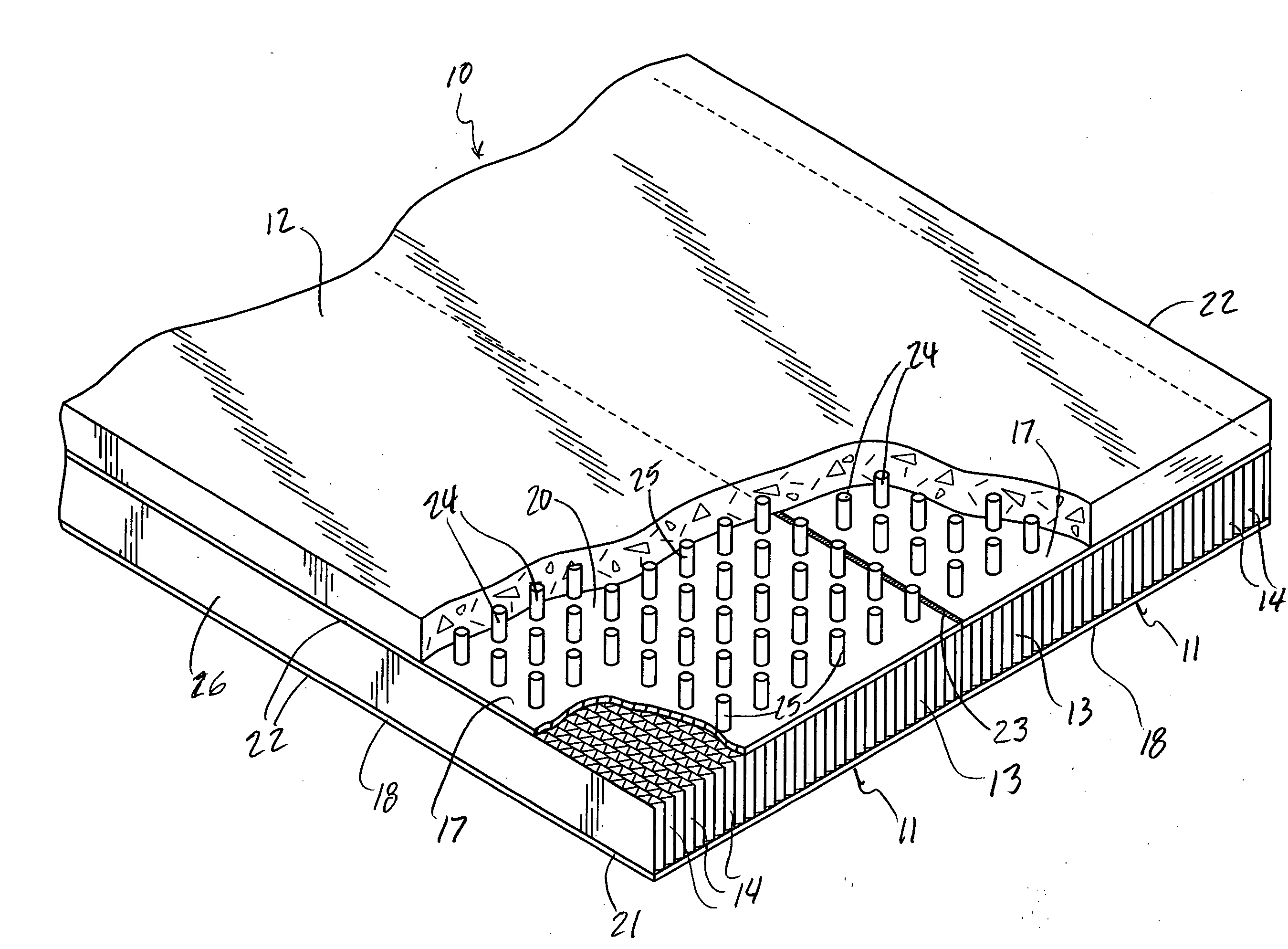
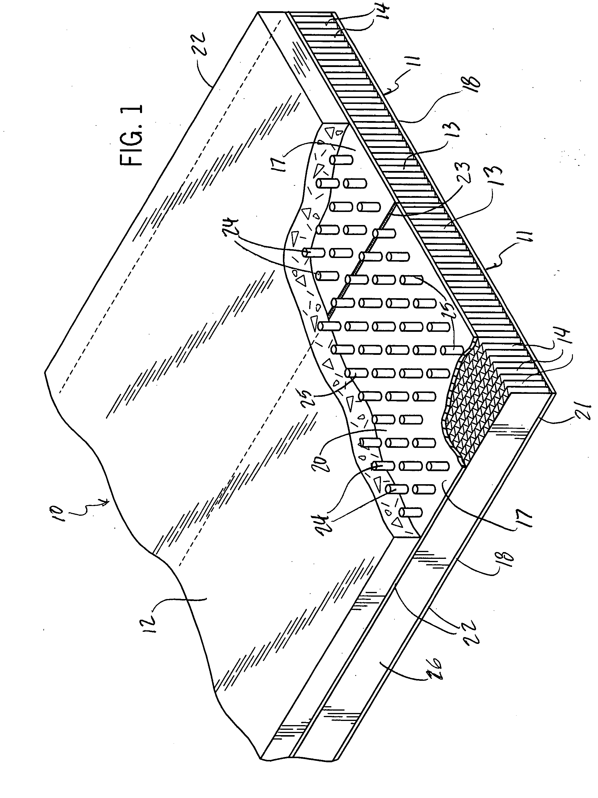
[0010]Referring first to FIG. 1, there is shown a portion of a deck 10 or floor useful, for example, in the construction of a bridge or a building, in which a series of long and relatively narrow modules 11 are joined together and covered with a poured concrete slab 12. Each of the modules 11 could be made of any desired dimensions, but for use in a floor deck, for example, module 11 could have a depth or thickness of 16 in., a width of 8 ft. and a length of 50 ft. To fabricate a deck 10 50 ft. long and 64 ft. wide, eight modules 11 would be joined along their long edges, as partly shown in FIG. 1.

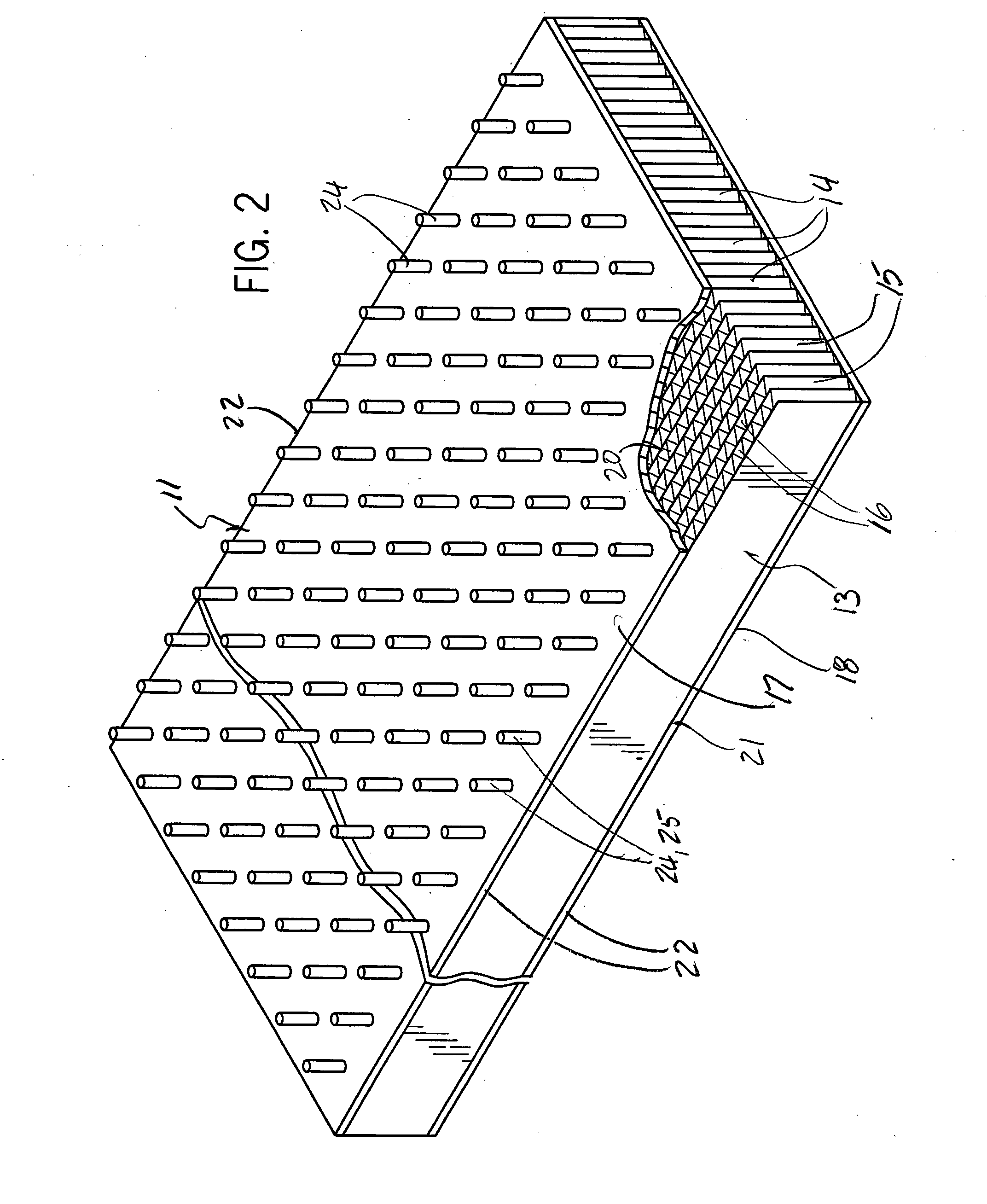
[0011]Each deck module 11 includes a hollow core element 13 of the type described and manufactured in accordance with the method disclosed in my above identified patent application. The hollow core element 13 includes a stack of long, narrow corrugated paperboard strips 14, each of which in the embodiment shown comprises a fluted web 15 and a smooth web 16 joined with a suitable adhesive. ...


PUM

PropertyMeasurementUnit
widthaaaaaaaaaa
lengthaaaaaaaaaa
lengthaaaaaaaaaa

Abstract

A composite structural support which may be utilized as a beam or assembled with similar supports to form a building floor or a bridge deck utilizes an open core element, made preferably of suitably treated fluted paper, upper and lower thin steel skins, and a layer of concrete poured over the top skin. Modules comprising the hollow core element and the upper and lower steel skins are fabricated to lengths required for building floor and bridge spans and, when joined by welding the upper and lower skins of adjacent elements along their full lengths, provide a floor or deck structure of a large span

Description

BACKGROUND OF THE INVENTION[0001]The present invention pertains to a lightweight hollow core structural building element which can be used as a beam or can be joined with other elements to form a floor or deck panel.[0002]The potential for the use of hollow core elements in the construction of buildings and other structures has been known for many years. Hollow cores of corrugated or honeycomb paper or metal sheet material, enclosed by upper and lower skin panels or sheets, have long been used or proposed for use as floor, wall and roof panels for buildings. However, the use of such hollow core panels has been inhibited because of difficulties in fabricating the panels in an efficient and cost effective manner.[0003]In my co-pending patent application Ser. No. 11 / 476,474, entitled “Method and Apparatus for Manufacturing Open Core Elements from Web Material”, filed Jun. 28, 2006, which application is incorporated by reference herein, there is disclosed a system for manufacturing holl...

Claims


Application Information

Patent Timeline
Patent Type & Authority Applications(United States)
IPC IPC(8): E04F13/04E04B9/00
CPCE01D19/125E01D2101/00E01D2101/268E01D2101/34E04C2/365E04B5/026E04B5/04E04B5/40E04B5/43E01D2101/40
Inventor MARSCHKE, CARL R.
Owner MARSCHKE CARL R
Why Eureka
Try Eureka