
Thermoelectric sensor for analytes in a gas and related method

a technology of analytes and thermoelectric sensors, applied in the direction of instruments, material heat development, diagnostic recording/measuring, etc., can solve the problems of inability to fully realize the full potential of blood chemistry, laborious, painful blood analysis, etc., and achieve the effect of enhancing such conta

Inactive Publication Date: 2008-03-06
AHMAD LUBNA M
View PDF53 Cites 50 Cited by
  • Summary
  • Abstract
  • Description
  • Claims
  • Application Information

AI Technical Summary

Benefits of technology

[0013]The invention comprises systems, apparatus and methods for sensing at least one analyte in a gas stream. Various aspects of the invention include controlling the...

Problems solved by technology

Historically, breath chemistry has not been very well exploited.
Blood analysis is painful, laborious, relatively expensive and often impractical due to lack of equipment or trained personnel.
While these companies have made home-testing possible, blood tests are still expensive and painful and they require careful disposal and procurement of needed equipment such as needles and collection vessels.
This leads to low patient compliance.
Urine analysis has been criticized as being inaccurate.
Thus, while blood and urine tests can provide information about the physiological state of an individual, they have been relatively unattractive or ineffective for practical application where portability or field or home use is required.
Current systems used to sense an analyte in a gas, such as gas chromatographs and spectroscopy-related devices, are expensive, cumbersome to use, they require skilled operators or technicians, and otherwise typically are not practical for field or home use.
They also tend to be quite expensive.
Precision in detection systems usually comes at substantial cost.
Current highly-accurate detection systems require expensive components such as a crystal, specialized power source, or containment chambers that are highly pH or humidity regulated.
However, the thermopile sensor is limited to measuring a single analyte and only a single reactant is present on the thermopile.

Method used


Image

  • Thermoelectric sensor for analytes in a gas and related method
  • Thermoelectric sensor for analytes in a gas and related method
  • Thermoelectric sensor for analytes in a gas and related method

Examples


Embodiment Construction

[0052]Reference will now be made in detail to the presently preferred embodiments and methods of the invention as illustrated in the accompanying drawings, in which like reference characters designate like or corresponding parts throughout the drawings. It should be noted, however, that the invention in its broader aspects is not limited to the specific details, representative devices and methods, and illustrative examples shown and described in this section in connection with the preferred embodiments and methods. The invention according to its various aspects is particularly pointed out and distinctly claimed in the attached claims read in view of this specification, and appropriate equivalents.

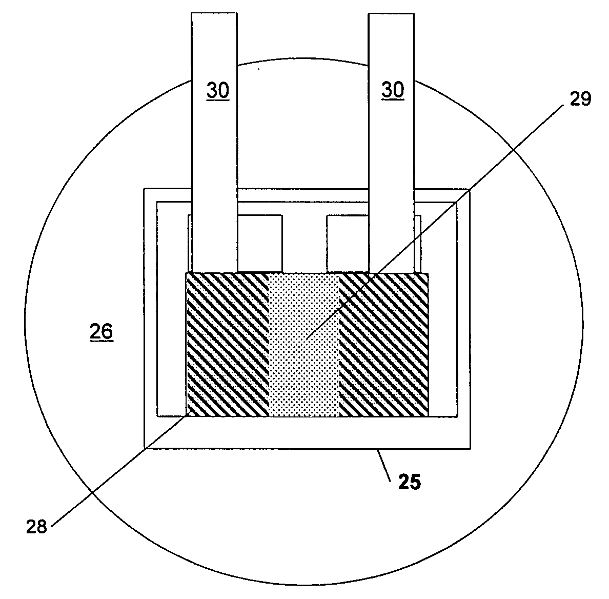
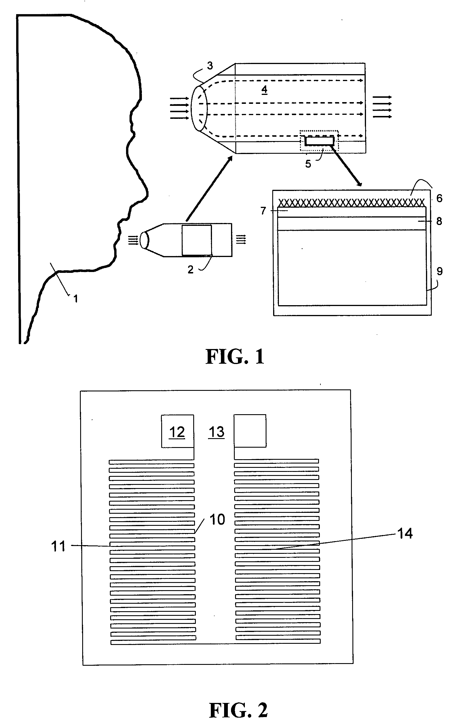
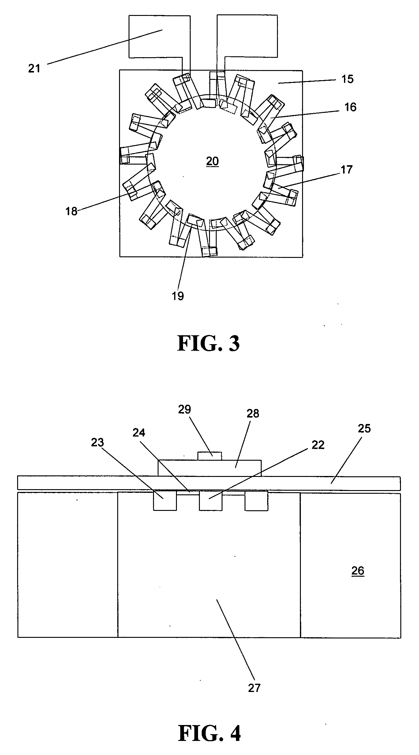
[0053]In accordance with one aspect of the invention, an apparatus is provided for sensing an analyte in a gas. To illustrate this aspect of the invention, an analyte-in-gas sensor 2 according to a presently preferred embodiment of this aspect of the invention is shown in FIG. 1 in conjunct...


PUM


Abstract

An apparatus for sensing an analyte in a gas. The apparatus includes a gas collecting device within the apparatus for collecting the gas containing the analyte, a gas input in fluid communication with the gas collecting device for inputting the gas containing the analyte into the gas collecting device, an analyte interactant in fluid communication with the gas collecting device, wherein the analyte interactant, when contacted by the analyte, reacts to cause a change in thermal energy within the gas collecting device, the anlayte interactant being disposed in a plurality of regions separate from one another, a thermopile device comprising at least one thermopile thermally coupled to the gas collecting device to generate a signal in response to the change in thermal energy, wherein the signal comprises information useful in characterizing the analyte. A related method also is disclosed.

Description

RELATED APPLICATIONS [0001]This patent application is a continuation-in-part of U.S. application Ser. No. 11 / 593,144, filed on Nov. 2, 2006, which is a continuation-in-part of U.S. application Ser. No. 11 / 273,625, filed on Nov. 14, 2005, which is a continuation-in-part of U.S. application Ser. No. 10 / 554,801, filed on Oct. 28, 2005, directed to a Thermoelectric Sensor for Analytes in a Gas, which claims priority based on PCT / US2004 / 013364, filed on Apr. 28, 2004, which claims priority to Application No. 60 / 465,949, filed on Apr. 28, 2003, the contents of each of which are hereby incorporated by reference in their entirety.BACKGROUND [0002]1. Field[0003]The invention relates generally to apparatus and methods for sensing analytes in a gas. A preferred example involves the sensing of one or more analytes in air or a gas expired by an individual for monitoring biochemical processes such as in diabetes, epilepsy, weight loss, and others.[0004]2. Background[0005]There are many instances ...

Claims


Application Information

Patent Timeline
IPC IPC(8): G01N25/20
CPCA61B5/08G01N33/497G01N25/4873G01N25/482A61B5/082
Inventor AHMAD, LUBNA M.
Owner AHMAD LUBNA M
Learn More