Air-intake apparatus
a technology of air intake and air intake, which is applied in the direction of mechanical equipment, machines/engines, combustion air/fuel air treatment, etc., can solve the problems of poor mileage of internal combustion engines, reduced filling efficiency of each cylinder with intake air, etc., and achieves the effect of reducing the variation of air flow among intake manifolds and reducing the loss of pumping
- Summary
- Abstract
- Description
- Claims
- Application Information
AI Technical Summary
Benefits of technology
Problems solved by technology
Method used
Image
Examples
first embodiment
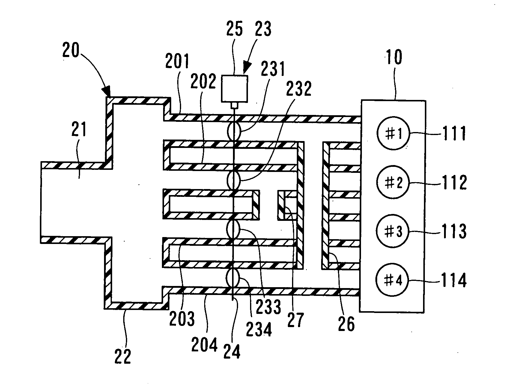
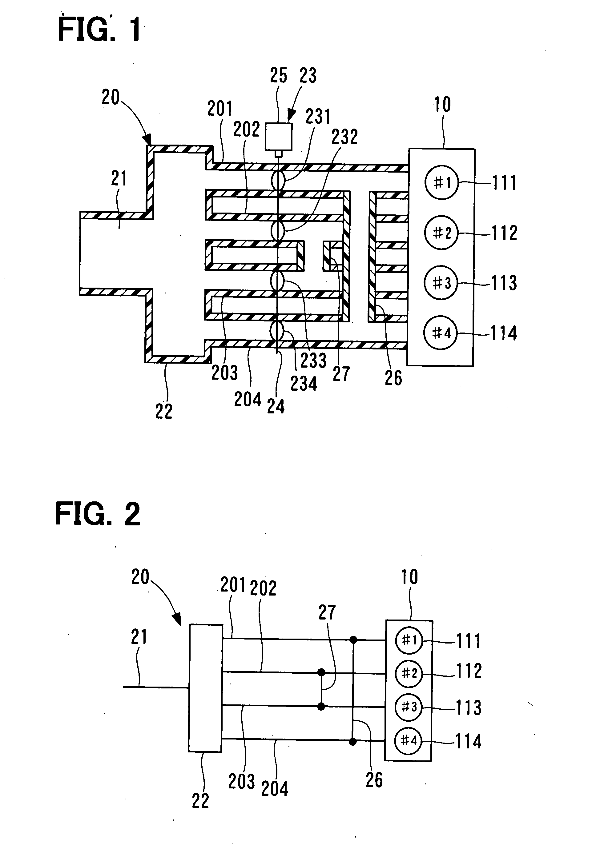
[0031]FIGS. 1, 2 show a gasoline engine as an internal combustion engine, employing an air-intake apparatus according to a first embodiment of the present invention. In FIGS. 1, 2, an example is shown, in which the air-intake apparatus according to the first embodiment is applied to a four-cylinder gasoline engine 10. FIG. 1 is a schematic partial cross sectional view of the gasoline engine 10, to which the air-intake apparatus according to the first embodiment is applied. FIG. 2 is a schematic view showing a configuration of passages, through which air to be drawn into the gasoline engine 10 in FIG. 1 flows.
[0032]An air-intake apparatus 20 is installed in the gasoline engine 10. The gasoline engine 10 has four cylinders. The four cylinders are arranged such that a first cylinder (#1) 111, a second cylinder (#2) 112, a third cylinder (#3) 113, and a fourth cylinder (#4) 114 are placed in this order from before backward in a traveling direction of a vehicle in which the gasoline engi...
second embodiment
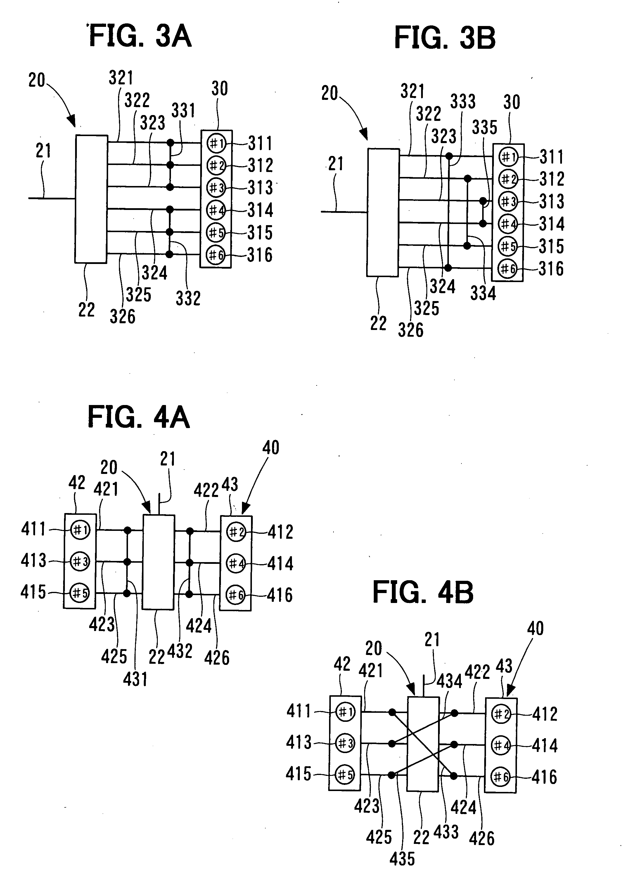
[0046]FIGS. 3A, 3B show a gasoline engine, in which an air-intake apparatus according to a second embodiment of the present invention is employed. A gasoline engine 30 shown in FIGS. 3A, 3B has serially-arranged six cylinders. The serially-arranged six-cylinder gasoline engine 30 has six cylinders, that is, a first cylinder 311, a second cylinder 312, a third cylinder 313, a fourth cylinder 314, a fifth cylinder 315, and a sixth cylinder 316 in this order from before backward in a traveling direction of a vehicle. Intake manifolds 321, 322, 323, 324, 325, 326 corresponding to each cylinder connect a surge tank 22 and the gasoline engine 30. In the case of the serially-arranged six-cylinder gasoline engine 30, mixed gas is combusted in, that is, mixed gas is ignited in the first cylinder 311, the fifth cylinder 315, the third cylinder 313, the sixth cylinder 316, the second cylinder 312, and the fourth cylinder 314 in this order. A combustion interval, that is, an ignition interval b...
third embodiment
[0053]FIGS. 4A, 4B show a gasoline engine, in which an air-intake apparatus according to a third embodiment of the present invention is employed. A gasoline engine 40 shown in FIGS. 4A, 4B is a V-six engine. The V-six gasoline engine 40 has a bank block 42 and a bank block 43. The bank block 42 has three cylinders, that is, a first cylinder 411, a third cylinder 413, and a fifth cylinder 415 in this order from before backward in a traveling direction of a vehicle. The bank block 43 has three cylinders, that is, a second cylinder 412, a fourth cylinder 414, and a sixth cylinder 416 in this order from before backward in the traveling direction of the vehicle.
[0054]A surge tank 22 is deposed between the bank block 42 and the bank block 43 of the gasoline engine 40. The surge tank 22 may be disposed independently corresponding to the bank block 42 and the bank block 43. Intake manifolds 421, 422, 423, 424, 425, 426 connect the surge tank 22 and the bank block 42, and the surge tank 22 a...
PUM
| Property | Measurement | Unit |
|---|---|---|
| Angle | aaaaa | aaaaa |
| Combustion | aaaaa | aaaaa |
Abstract
Description
Claims
Application Information
 - R&D
- Intellectual Property
- Life Sciences
- Materials
- Tech Scout
- Unparalleled Data Quality
- Higher Quality Content
- 60% Fewer Hallucinations
Browse by: Latest US Patents, China's latest patents, Technical Efficacy Thesaurus, Application Domain, Technology Topic, Popular Technical Reports.
© 2025 PatSnap. All rights reserved.Legal|Privacy policy|Modern Slavery Act Transparency Statement|Sitemap|About US| Contact US: help@patsnap.com


